Do you have a question about the Vectornav VN-200 and is the answer not in the manual?
Describes the VN-200 as a miniature, high-performance Inertial Navigation System (INS) with MEMS sensor technology.
Highlights the VN-200's availability in surface-mount and rugged configurations, emphasizing robust enclosure and small footprint.
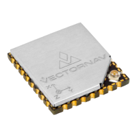
Details the miniature surface-mount package of the VN-200, suitable for embedded applications, including its dimensions and interfaces.
Describes the VN-200 Rugged sensor integrated into a robust aluminum enclosure, focusing on its durability and compact size.
Introduces the development kit for the VN-200 SMD, providing PCB access, communication ports, and necessary accessories.
Outlines the VN-200 Rugged Development Kit, including the sensor, necessary cabling, documentation, and software.
Explains the VN-200's right-handed coordinate system and the definition of yaw, pitch, and roll angles.
Details the electrical specifications and pin assignments for the VN-200 Surface-Mount Sensor (SMD).
Specifies the operating voltage range for the VN-200 SMD, including minimum and absolute maximum values.
Describes the voltage logic levels for the serial UART interface of the VN-200 SMD.
Provides serial I/O specifications for the SPI interface of the VN-200 SMD, including clock frequency and timing.
Details specifications for Reset, SyncIn/Out, and other general I/O pins on the VN-200 SMD.
Details the electrical specifications and pin assignments for the VN-200 Rugged model.
Specifies the nominal power supply and overvoltage protection for the VN-200 Rugged unit.
Details the serial I/O specifications for the UART interface of the VN-200 Rugged, including voltage levels and data rates.
Details specifications for Reset, SyncIn/Out, and other general I/O pins on the VN-200 Rugged.
Provides PCB footprint dimensions for the VN-200 Surface-Mount Sensor (SMD).
Illustrates the physical dimensions of the VN-200 Rugged sensor with detailed measurements in inches.
Lists the absolute maximum ratings for input voltage, operating temperature, and storage temperature for the VN-200.
Explains the serial interface, using ASCII text for commands and data, with a specific command format.
Details options for error detection using 8-bit checksum or 16-bit cyclic redundancy check (CRC).
Explains the 8-bit checksum calculation as an XOR of bytes, represented by two hexadecimal characters.
Describes the 16-bit CRC using the CRC16-CCITT algorithm for enhanced error detection.
Details the SPI interface using a binary message format, triggered by slave select and clock signals.
Explains floating-point and fixed-point number representations used in commands and data output.
Details the format for single-precision floating-point numbers with seven significant digits and a two-digit exponent.
Describes fixed-point representation and notes that onboard calculations use IEEE floating-point numbers.
Lists available system commands for the VN-200, usable via ASCII text (UART) and binary (SPI) formats.
Allows reading registers by ID. Response includes register ID and data specific to the register.
Used to write data to specified registers, requiring register ID and specific data values.
Writes current register settings to non-volatile memory, ensuring persistence through power cycles.
Resets the VN-200 module to its factory default settings and initiates a module reboot.
Resets the module, reloading registers from non-volatile memory or defaulting to factory settings.
Lists VN-200 error codes outputted after '$VNERR', providing descriptions for each error condition.
Allows assignment of user-defined tags, stored to flash via a write settings command.
A read-only register that stores and displays the model number of the VN-200 device.
A read-only register that displays the hardware revision of the VN-200 module.
A read-only register containing the unique serial number of the VN-200 device.
A read-only register detailing the major, minor, build, and hotfix versions of the VN-200 firmware.
Specifies the baud rate for the serial data bus, with an optional parameter for serial port selection.
Controls the type of data asynchronously outputted, allowing selection of data registers or disabling output.
Sets the output frequency for asynchronous data, with an option for serial port selection.
Stores magnetic and gravity reference vectors for X, Y, and Z axes, and acceleration references.
Contains a transformation matrix to rotate measurements into a different reference frame, useful for sensor orientation.
Manages communication protocol settings, including counters, status, checksums, and error handling.
Appends a counter or time to serial asynchronous messages, sourced from the Synchronization Status Register.
Tracks real-time status information for sensor measurements and filtering, useful for critical event detection.
Appends a counter or time to SPI packets, sourced from the Synchronization Status Register.
Tracks real-time status information for sensor measurements and filtering in SPI communication.
Controls the type of checksum (8-bit or 16-bit CRC) for serial communications.
Controls the type of checksum (8-bit or 16-bit CRC) for SPI communications.
Determines the action taken when an error event occurs, such as ignoring, sending, or disabling output.
Manages timing synchronization with external devices via SyncIn and SyncOut pins.
Controls the SyncIn event behavior, setting ADC timing or asynchronous output on trigger.
Defines the edge type (rising or falling) for the SyncIn signal to trigger on.
Determines how many trigger edges must occur before a SyncIn event is triggered.
Controls the behavior of the SyncOut pin, determining when the pulse starts based on ADC, IMU, or INS data.
Sets the polarity of the output pulse on the SyncOut pin to either negative or positive.
Specifies how many times the sync out event should be skipped before triggering the SyncOut pin.
Controls the desired width of the pulse output on the SyncOut pin.
Provides calibrated measurements from all onboard sensors, including magnetometer, accelerometer, gyroscope, temperature, and pressure.
Configures GPS settings, including mode, NMEA output on serial ports, and GPS delay for PPS support.
Configures the position offset of the GPS antenna relative to the VN-200 in the vehicle reference frame.
Provides GPS solution data, including time, week, fix type, position, velocity, and accuracy estimates.
Provides INS solution data, including time, status, heading, pitch, roll, position, velocity, and uncertainties.
| Brand | Vectornav |
|---|---|
| Model | VN-200 |
| Category | Microcontrollers |
| Language | English |