-
1290K Instruction Manual AM Radio Transmitter Kit
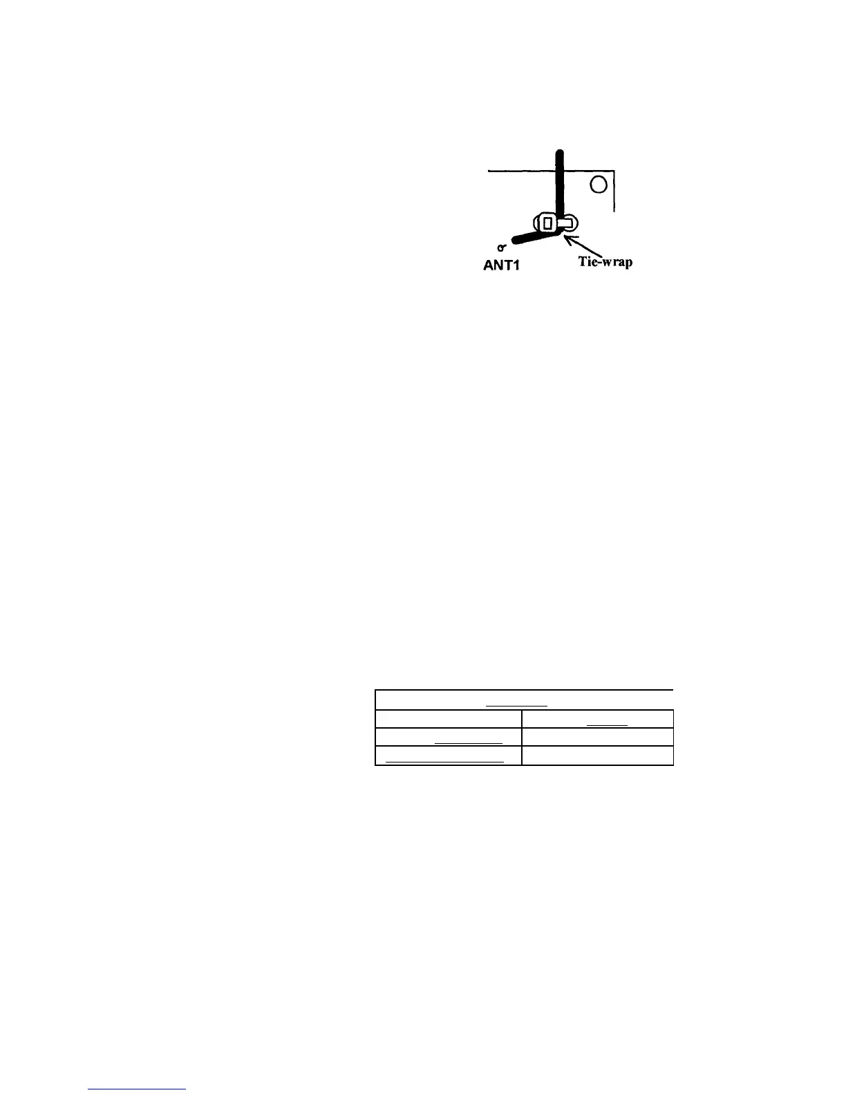
7. Find the 4" nylon wire tie. Secure the antenna wire to the PC board
using the wire tie as shown below. Pull the tie wrap tight, and trim
excess tie len
th.
8. Locate the two plastic shorting jumpers. Put these in the parts bag
until needed for the ali
nment
rocedures.
9. This completes the assembly of the VEC-1290K AM radio transmitter.
Please go over the board and verify that all parts are properly
installed. Check all solder connections, and redo those that look
suspect.
TESTING AND ALIGNMENT
Before attempting any adjustments, the entire section dealing with Alignment
and Testing should be read, and some familiarity with the Operating
Instructions section is also advisable. The transmitter requires a suitable
external power and audio source for alignment and operation.
Initial alignment sets the transmitter to the desired operating segment of the
AM broadcast band. The VEC-1290K oscillator stage covers the AM band in
three preset ranges. These are determined by the presence or absence of a
jumper at locations JMP1 and JMP2. Fine tuning within each of the
three ranges is set by trimmer capacitor C12.
Oscillator frequency ran 'reset
,
540kHz to 870kHz no jumper
870kHz to 1420kHz JMP1
1 l70kHz to l7l0kHz
Table 1
 Loading...