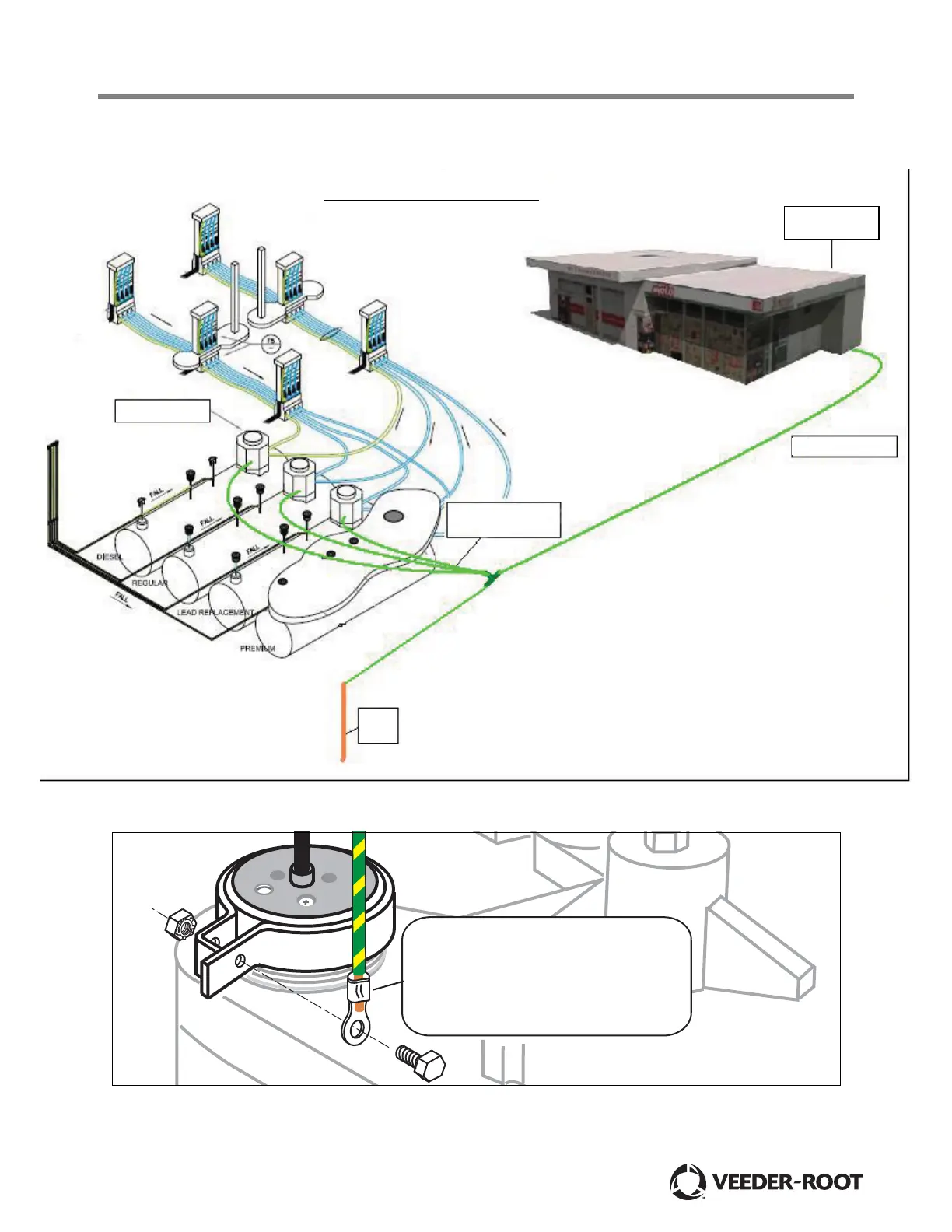
Figure 1.
Figure 2.
16mm earth to DB
2
STP in tank sump
4mm (minimum)
earth to each
PLLD sensor
2
Earth
spike
Recommended Earth Layout for PLLD sites
1. Site has 16mm earth (typical) to each tank sump.
2. All sump earths are connected to common point.
3. From the common point, earth is connected to an
Earth spike.
4. From the common point, earth is also connected
to the building earth in the distribution panel.
Building electrical
distribution panel
2
012-3.eps
Securely crimp stripped barrier wire
in ring terminal. Slip ring terminal
onto bolt and screw bolt into clamp
nut. Tighten bolt until the clamp
cannot be rotated by hand.