63138-US-200110 49
5.5 Compressed Air Connection
These instructions apply to the SHLD 2 source holders with a pneumatic
switching mechanism. Do not put the pneumatic switching mechanism into
operation until after the source holder is mounted.
Connecting Pneumatic Lines
The pneumatic line is connected outside on the threaded
hole.
A connection
adapter appropriate to the ordered thread type is attached.
Tighten the pneumatic line and make sure there are no leaks in the entire air line.
In case of a leak, the pneumatic switching mechanism switches automatically to
the "OFF" position (spring pressure) as soon as the pressure in the air line falls
below 4 bar (58 psi).
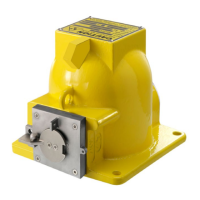
Figure 5.2
Connection of Pneumatic Lines (with Pneumatic Switching Mechanism)
1. Padlock for securing the switch position "OFF"
2. Ventilation filter
3. Indication of the switching position
4. Threaded hole for connection of the compressed air (optionally with connection adapter)
5. Locking bolt
6. Retention hole for locking bolt
7.
Cable protection
 Loading...