8 Compare
the settings of the two electronics modules. Set the
adjustment elements of the new electronics module to the same
setting of the old one.
Information:
Make sure that the housing is not rotated during the electronics
exchange. Otherwise the plug may be in a different position later.
9 Insert the electronics module carefully. Make sure that the plug is
in the correct position.
10 Screw in the two holding screws and tighten them
11 Insert the wire ends into the open terminals according to the wiring
plan
12 Press down the opening levers of the terminals, you will hear the
terminal spring closing
13 Check the hold of the wires in the terminals by lightly pulling on
them
14 Check cable gland on tightness. The seal ring must completely
encircle the cable.
15 Mount the probe into the vessel. Make sure that the probe is
uncovered.
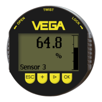
Fig. 2: Compensation
key
1 Measuring range selection switch (compensation key)
2 Control lamp
16 Push the measuring range selection switch (1) as long as the
control lamp (2) flashes green.
17 Hence the probe is compensated to the modified length.
18 Carry out the adjustment again. See chapter "Set-up, adjustment
elements".
19 Screw the housing cover back on
The electronics exchange is now finished.
As a rule, an exchange of electronics must be documented internally
when Ex applications are involved.
Ele
ctronics module • VEGACAP series 60 7
4 M
ounting
30174-EN-120124
 Loading...