17
5 Connecting to the sensor
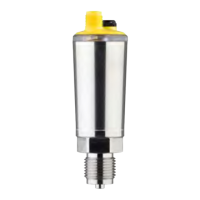
VEGADIS 81 •
43814-EN-170913
9. Tighten the compression nut of the cable entry gland. The seal
ring must completely encircle the cable
10. Reinsert the display and adjustment module, if one was installed
11. Screw the housing lid back on
5.3 Wiring plan
3
2
1
Display
Fig. 12: Electronics and terminal compartment VEGADIS 81
1 Contact pins for the display and adjustment module
2 Spring-loaded terminals for connection of the sensor
3 Ground terminal for connection of the cable screen
Electronics and terminal
compartment

 Loading...