6
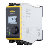
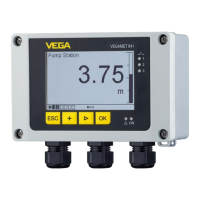
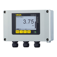
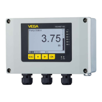
VEGAMET 141, 142
63696-EN-210721
8 Electricaldata
VEGAMET141,142
Non-intrinsicallysafecircuit
Supplycircuit:
Terminals 91[+, L], 92[-, N] U = 24 … 65 V DC (-15 … +10 %)
P = 3 W (VEGAMET 141), 4 W (VEGAMET 142)
U = 100 … 230 V AC (-15 … +10 %), 50/60 Hz
P = 10 VA (VEGAMET 141), 12 VA (VEGAMET 142)
U
m
= 253 V AC
Relayoutput:
Relay 1: terminals 61, 62, 63
Relay 2: terminals 64, 65, 66
Relay 3: terminals 67, 68, 69
1 A AC (cos phi > 0.9), 250 V AC, 250 VA
1 A DC, 60 V DC, 40 W
U
m
= 253 V AC
Currentoutputcircuit:
I
out
1, terminals 41[+], 42[-]
In addition only VEGAMET 142:
I
out
2, terminals 43[+], 44[-]
I = 0/4 … 20 mA
U ≤ 16 V DC
Load ≤ 500 Ohm
U
m
= 253 V AC
Intrinsicallysafecircuit
Supplyandsignalcircuit:
4 … 20 mA sensor 1: Terminals 1[+], 2[-],
Service socket [HART1]
In addition only VEGAMET 142:
4 … 20 mA sensor 2: Terminals 4[+], 5[-],
Service socket [HART2]
In type of protection intrinsic safety Ex ia IIC, IIB/IIIC.
For connection to a certied, intrinsically safe circuit.
U
o
/V
oc
≤ 23.3 V DC
I
o
/I
sc
≤ 109.8 mA
P
o
≤ 639.6 mW
Characteristics: linear
C
i
negligibly small
L
i
negligibly small
The maximum values given in the table can be used as concentrat-
ed capacitances and concentrated inductances.
The values for IIC and IIB are also permissible for dust explosive
areas.
Ex ia IIC, Grp A, B IIB, Grp C or IIIC, Grp
E, F, G
IIA, Grp D
Permissible external inductance L
o
/L
a
0.2 mH 0.5 mH 0.5 mH 2 mH 10 mH
Permissible external capacitance C
o
/C
a
120 nF 88 nF 580 nF 470 nF 770 nF
Permissible outer L
o
/R
o
-ratio 55 µH/Ohm 55 µH/Ohm 221 µH/
Ohm
221 µH/
Ohm
443 µH/
Ohm
The HART1 and HART2 service sockets are directly connected to the intrinsically safe output termi-
 Loading...