17
7 Set up with the integrated display and adjustment unit
VEGAMET 141 • 4 … 20 mA
63728-EN-210129
7 Set up with the integrated display and
adjustment unit
7.1 Adjustment system
The integrated display and adjustment unit is used for measured
value display, adjustment and diagnosis of the VEGAMET 141. Dis-
play and adjustment are carried out via the central turn/push buttons
and a graphic-capable display with background lighting.
Certain setting options are not possible or only possible to a limited
extent with the integrated display and adjustment unit, for example the
settingsforowmeasurementorpumpcontrol.Fortheseapplica-
tions, the use of PACTware/DTM or the VEGA Tools app is recom-
mended. A tabular overview of the corresponding applications and
functions can be found in the appendix.
2
3
4
1
5
6
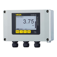
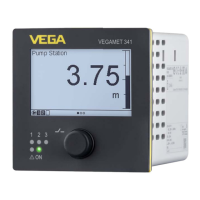
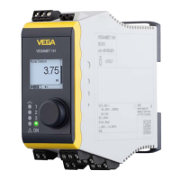
Fig. 5: Display and adjustment elements
1 LC display
2 Status indication relay
3 Status indication fault signal
4 Status indication operation
5 Turn/push button for menu adjustment
6 HART communication sockets
Via the HART communication sockets, a parameter adjustment of
the connected HART sensors can be carried out without interrupting
themeasuringcircuit.Theresistorrequiredforthispurpose(230Ω)
is already integrated in VEGAMET 141. The sockets have an inner
diameter of 2 mm for direct connection of a VEGACONNECT or other
HART modems. The adjustment of the connected sensor is carried
out via the VEGA Tools app or via PACTware and appropriate DTM.
Function
Display and adjustment
elements
HART communication
sockets
 Loading...