8
Polarisation lock VEGAPULS 64, 69 • 4 … 20 mA
54812-01-191211
2 Product description
1 For your safety
1.1 Authorised personnel
All operations described in this documentation
must be carried out only by trained, qualied
personnel authorised by the plant operator.
During work on and with the device, the requi-
red personal protective equipment must always
be worn.
1.2 Appropriate use
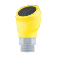
The housing lock (Polarisation lock) is an ac-
cessory component for VEGAPULS 64 and 69
radar sensors.
You can nd detailed information about the area
of application in chapter "Product description".
Operational reliability is ensured only if the inst-
rument is properly used according to the speci-
cations in the operating instructions manual as
well as possible supplementary instructions.
1.3 Warning about incorrect use
Inappropriate or incorrect use of the instrument
can give rise to application-specic hazards,
e.g. vessel overll or damage to system compo-
nents through incorrect mounting or adjustment.
1.4 General safety instructions
The safety information in the operating
instructions manual of the respective sensor
must be noted.
2 Product description
2.1 Conguration
Scope of delivery
The scope of delivery encompasses:
•
Housing lock with mounting screws
•
Adjusting ring from 42 to 40 mm diameter
•
Documentation
– These mounting instructions
Version
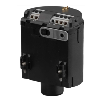
The housing lock consists of two clamp collars
connected by hexagon socket screws. It is suita-
ble for all sensor housings of the plics
®
family.
1
2
Abb. 8: Housing lock
1 Clamp collars
2 Hexagon socket screws
2.2 Principle of operation
Application area
Turning the housing of VEGAPULS 64 and 69
radar sensors changes the polarization of the
radar signals. This inuences the eect false
echoes have on the measured value.
The housing lock xes the orientation of the
housing with respect to the process tting.
This makes it possible to secure an optimal
measuring position once it has been found. The
housing lock can be retrotted at any time, even
during operation. It is not necessary to dismount
or electrically disconnect the sensor.
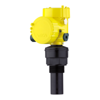
The clamp collars have dierent contours that
t the respective sensor housing. Sensors with
plastic horn antenna have a clamping diame-
ter of 40 or 42 mm depending on the device
generation. To adapt to the respective diameter,
the supplied ring is inserted between the clamp
collars.
The following illustrations show the mounting
positions for the dierent housing versions.
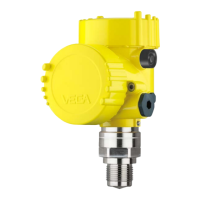
1 2
4
3
Abb. 9: Housing lock with plastic housing
1 Single chamber housing
2 Double chamber housing
3 Housing
4 Housing lock
 Loading...