Function as interface
Function of outputs
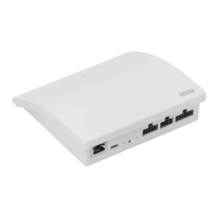
OUTPUT A connects to INPUT 1 and 2.
OUTPUT B connects to INPUT 3 and 4 etc.
The output function is used together with an intelligent building instal-
lation (IBI) to get feedback from KLF 200. The output function gives the
user feedback as to whether an action has been executed, for instance
if the skylight has been closed. As feedback, the built-in output relay is
activated for 2 seconds.
Intelligent building installations
io-homecontrol
®
products can be combined with most intelligent building
installations (IBI). The IBI system must include an output module with
one or more programmable outputs. When the outputs from the IBI have
been connected to the input terminals on the interface, the relevant
io-homecontrol
®
products can be controlled via the interface. With two
outputs it is possible to control both function and function in an
io-homecontrol
®
product or a group of io-homecontrol
®
products.
Function as interface
Resetting
Change of configuration
Press the RESET button on the back of the interface for ten seconds with
a pointed object until the red light-emitting diode is on. Subsequently, the
light-emitting diode turns yellow followed by a red flash.
When the light-emitting diode flashes yellow, the interface has been
reset. This may take up to 1 min.
Resetting
When resetting, all settings will be deleted and the interface reset to
factory settings.
Change of configuration
For more advanced settings via computer, tablet or smartphone, see sup-
plementary instruction
B
enclosed with the product.

 Loading...