INSTALLATION/USE/MAINTENANCE GUIDE
ISO 9001:2000 - Cert. n. 1368/1
UNIT INSTALLATION
RECOMMENDATIONS FOR INSTALLATION!
Before installing the unit, ensure that:
1) the place of installation has sufficient space for carrying out installation as well as routine
and extraordinary maintenance work (see fig. 3). If the unit is installed behind a
suspended ceiling, an access should be provided;
2) there are no obstructions for air intake and delivery;
3) the water fittings are of the sizes, in the position and spaced apart as required by the
unit;
4) the system pressure does not exceed 8 bar for the water-filled versions;
5) the electricity supply corresponds to the data on the unit rating plate and that there is
a circuit breaker switch readily accessible to the user to cut off the power supply
whenever necessary;
6) the circuit breaker is in the OFF position so that there is no voltage on the unit supply
line.
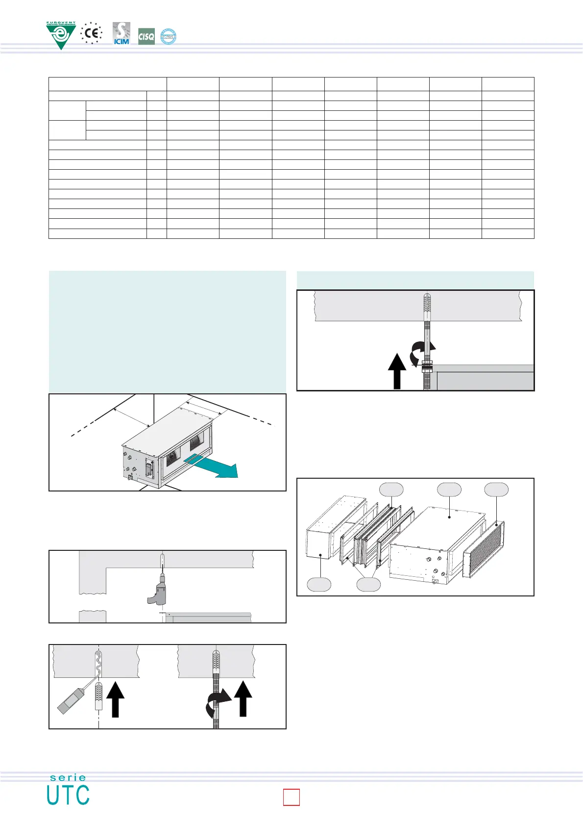
GENERAL TECNICHAL DATA
Tab. 2
possible noise being created by vibrations from the unit, it is advisable to insert a vibration-
damping joint.
N.B.: the screw anchors, threaded rods and whatever else is necessary for accomplishing
the installation are NOT included in the supply of the air treatment unit.
INSTALLATION OF THE ACCESSORIES
Some examples are given below of assembling the accessories for ducted air
treatment units.
Example 1
First of all put the air filter section (SFA) on the unit intake, inserting it into the special
rim (male-female) and fixing it with the galvanised self-tapping screws 4.2x9.5.
Proceed as described above on the delivery end with the connecting flange (FAM).
Put the vibration isolation joint (GAM) on the flange and fix it using the cheese-
headed screws M8x16 and hexagon bolts.
INSTALLATION OF THE AIR TREATMENT UNIT
Preliminary operations:
- check that the various unit components are perfectly intact;
- check that the installation accessories and documentation are in the pack;
- place the packed section as close as possible to the place of installation;
- do not place tools or weights of any kind on the packed unit.
Fig. 3
P
1,5 P
Fig. 4
Drill the holes in line with the relative slots for the 6 unit screw anchors (fig. 4). Inject
thermosetting resin into the holes and then insert the screw anchors (fig. 5).
MODELLO UTC 10 UTC 20 UTC 30 UTC 40 UTC 50 UTC 60 UTC 70
Fans - Motors No.
Standard Rows No.
coil Fittings (ØAF) Ø
Auxiliary Rows No.
coil Fittings (ØAC) Ø
Cond. drain fitting (ØC) Ø mm
High (H) mm
Lenght (L) mm
Depht (P) mm
(A) mm
(B) mm
N. x Ø BAM mm
Net Weight kg
Max.power motor input W
Max.current motor input A
1-1 2-1 2-1 2-1 2-1 1-1 2-2
333 33 44
1/2" 1/2" 3/4" 3/4" 1" 1"1/4 1"1/2
111 11 22
1/2" 1/2" 1/2" 1/2" 3/4" 1" 1"1/4
20 20 20 20 20 20 20
299 299 324 324 374 674 674
650 1.000 1.100 1.339 1.339 1.341 2.028
533 533 533 533 533 853 853
197 197 222 222 272 572 572
548 898 998 1.237 1.237 1.239 1.926
2xØ200 3xØ200 3xØ200 4xØ200 4xØ200 2xØ200 4xØ200
28 26 41 46 57 117 192
162 218 322 340 582 1.320 2.600
0,72 0,97 1,43 1,51 2,58 5,86 11,54
Fig. 5
Fig. 6
Fix the threaded rods of the correct length to the screw anchors (fig. 5) and insert them
into the relative slots (fig. 6). After having created a slope (max. 3 cm/m) in the direction
of the condensate outlet, lock the threaded rod with a nut and check nut. To prevent
Example 2
Proceed by inserting the manual air intake section (SSP) into the air filter section (SFA) by
means of the male-female coupling. After having secured it with the self-tapping screws (4.2
x 9.5 galvanised), anchor it to the ceiling as illustrated for the base unit in figures 4-7. Put
another connecting flange on the vibration isolation joint (GAM) and secure it using cheese-
headed screws M8x16 and hexagon bolts. Insert the straight delivery plenum (PAM) in the
connecting flange and fix it using galvanised self-tapping screws 4.2 x 9.5. Connect the air
delivery union with round fittings (BAM) with the procedure described above.
Electrical supply: 230 V/1/50 Hz
GAM
PAM FAM
UTC SFA
Fig. 7
4
 Loading...