Measurements per EIA standards unless noted above. Specifications subject to change without notice or obligation.
2001.02NA(U)
B9200338 Printed in Japan
General Specifications
Frequency Range 134-160 MHz (A)
400-430 MHz (AS1)
148-174 MHz (C) 450-485 MHz (D)
485-512 MHz (F)
Number of Channels
16 Channels
Channel Spacing 15/30 kHz 12.5/25 kHz
PLL Steps 2.5/6.25 kHz 5/6.25 kHz
Power Supply Voltage
7.5 VDC ±
20 %
Battery Life (5-5-90 duty)
w/FNB-V57(1100 mAh)
8.2 hrs. (9.9 hrs. w/saver) @5 W 7.1 hrs. (8.5 hrs. w/saver) @5 W
w/FNB-64 (700 mAh)
5.2 hrs. (6.3 hrs. w/saver) @5 W 4.5 hrs. (5.4 hrs. w/saver) @5 W
Operating Temperature Range
–22° F to
+
140° F (–30° C to
+
60° C)
Frequency Stability ±2.5 ppm
Dimensions 2.3" (W
)
X4.7" (H
)
X1.2" (D
)
(58X120X31 mm
)
Weight (Approx) 0.81 lb. (365 g) w/FNB-64
VX-180V VX-180U
Standard
MIL 810C
Methods/Procedures
MIL 810D
Methods/Procedures
MIL 810E
Methods/Procedures
Low Pressure
High Temperature
Low Temperature
Temperature Shock
Solar Radiation
Rain
Humidity
Salt Fog
Dust
Vibration 514.2/Procedure 8
Shock 516.2/Procedure 1
500.2/Procedure 1
501.2/Procedure 1, 2
502.2/Procedure 1, 2
503.2/Procedure 1
505.2/Procedure 1
506.2/Procedure 2
507.2/Procedure 2
509.2/Procedure 1
510.2/Procedure 1
514.3/Procedure 1 Cat. 10
516.3/Procedure 1, 4
500.3/Procedure 1
501.3/Procedure 1, 2
502.3/Procedure 1, 2
503.3/Procedure 1
505.3/Procedure 1
506.3/Procedure 2
507.3/Procedure 2
509.3/Procedure 1
510.3/Procedure 1
514.4/Procedure 1 Cat. 10
516.4/Procedure 1, 4
Accessories & Options
Specifications
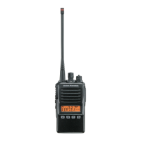
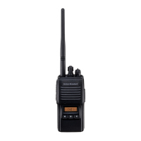
VX-180 SERIES
APPLICABLE MIL-STD
MIL-STD 810 C/D/E
Built to meet or exceed the requirements of the U.S. MIL-STD 810
C/D/E
standard. the VX-180 is designed to
survive under difficult operating conditions
of shock, vibration, and driving rain.
Cost-performance begins with durability,
and the Mil-Spec toughness of the VX-180
is your guarantee of its design quality.
SUPER RUGGED CONSTRUCTION
Housed inside a high-impact case, the diecast chassis of the VX-180
provides a solid, rugged foundation for the VX-180s circuitry. Built to
survive in the real world of factory, construction site, or fleet use, the
VX-180 will provide many years of reliable communications.
BCLO, BTLO, AND TOT
To facilitate efficient channel management, the VX-180 provides Busy Channel
Lock-Out (BCLO) and Busy Tone Lock-Out (BTLO) features. Whats more, the
transmitters Time-Out Timer (TOT) function prevents a stuck microphone
condition from jamming a channel for an extended period of time.
CTCSS / DCS ENCODE + DECODE
High-performance Encoder/Decoder circuits for both CTCSS and Digital
Code Squelch are provided, for access to tone/code controlled systems.
DCS is ideal for crowded RF environments, providing superior immunity
from false opening of squelch.
TX/RX BATTERY SAVER CIRCUIT
To maximize battery life, the VX-180 includes both transmit- and receive-
mode battery savers. On transmit, the portable will reduce power when
the incoming signal is very strong. On receive, the radio will put itself into
a pulsing sleep mode, periodically checking for channel activity.
PC PROGRAMMING
The channel and feature configurations are easily programmed in
minutes by the dealer, using the optional CT-42A Programming Cable
and CE44 Programming Software.
RADIO TO RADIO CLONE FEATURE
For quick programming of VX-180 radios for fleet use, the Clone
feature allows copying of all channel and other configuration data from
one VX-180 to another, using the optional CT-27 Cloning Cable.
500 mW AUDIO OUTPUT
Ideal for reception in noisy environments, the VX-180s high—powered
audio is coupled to a large internal speaker, assuring solid copy
throughout difficult construction site or field operations.
DTMF ANI DECODE
The VX-180 includes a DTMF Automatic Number Identifier (ANI) circuit,
which will respond to an incoming ANI burst for selective paging of an
individual portable.
VERSATILE SCANNING FEATURES
The high-speed scanning capability of the VX-180 includes All-Channel
scanning, plus Dual Watch and Priority Channel capability. And with
Follow-Me scanning, a designated channel may be watched during
scanning of other channels.
Included in the VX-180 is Vertex
Standards exclusive ARTS“
feature,
which can be critically
important in search-and-rescue
applications.
ARTS“ provides a
hand-shake with
other ARTS“-
equipped transceivers,
and the
display indicates if an Out of
Range condition exists. The base
VX-180V VX-180U
Receiver Specifications
Measurements made per EIA standard TIA/EIA-603
Sensitivity
EIA 12 dB SINAD
0.20 µV 0.25 µV
20 dB Quieting 0.30 µV 0.35 µV
Adjacent Channel Selectivity 65 dB
(25 kHz)
/ 60 dB
(12.5 kHz)
Intermodulation 65 dB
Spurious and Image Rejection
65 dB
Hum & Noise 45 dB
Audio Output 500 mW @4 Ohms, 5 % THD
Transmitter Specifications
Measurements made per EIA standard TIA/EIA-603
Power Output 5.0/1.0 W
Modulation 16K0F3E, 11K0F3E
Conducted Spurious Emissions
60 dB Below Carrier
FM Hum & Noise
40 dB (25 kHz) / 35 dB (12.5 kHz)
Audio Distortion
(
@1 kHz
)
<
5 %
CH-1
DCS No.003
ARTS“ Operation
CH-1
DCS
No.003
CH-1
DCS No.003
Out of Range
*ARTS: This system informs you when
you and another ARTS-equipped station
are within communications range.
Moving
This device has not been authorized as required by the rules of the Federal Communications Commission. This device is not, and may not be, offered for sale or lease, or sold or leased, until
authorization is obtained.
FNB-64
7.2 V 700 mAh Ni-Cd Battery Pack
FBA-25
Alkaline Battery Case(6
X
AA)
FNB-V57
7.2 V 1100 mAh Ni-Cd Battery Pack
VAC-6800
6-unit Multi Charger
VCM-1
Mobile Mounting Bracket for VAC-800
MH-45B4B
Speaker/Microphone (Noise Cancelling)
MH-37A4B
Earpiece/Microphone
VC-25
VOX Headset
CE44
Programming Software
CT-27
Radio to Radio Programming Cable
CT-42A
Radio Programming Cable
ARTS“ (Auto Range Transponding System)
VAC-800B/C
Desktop Rapid Charger
(B for 120 VAC/ C for 240 VAC)
NC-77B/C Wall Charger
(B for 120 VAC/ C for 240 VAC)
LCC-180 / S
Leather Case
(S for swivel belt clip)
8-CHARACTER ALPHANUMERIC DISPLAY
Providing indication of either the channel number or an
Alphanumeric Channel Label of up to 8 characters, the
LCD display also provides convenient operation function
icons to provide instant recognition of radio status.
3 PROGRAMMABLE OPERATING FUNCTION KEYS
Customization of feature access is easily
accomplished at the time of programming. Flexibility
in assignment of features ensures compatibility
with existing-system requirements.
•
Water Resistant Construction
DUAL 2-TONE DECODE
This built in feature allows you to decode up to two, 2-tone pairs per
channel. These can be used for two individual pager calls, or one for
Individual and one for Group call.
Vertex Standard
US Headquarters
10900 Walker Street, Cypress, CA 90630, U.S.A.
Phone 714/827-7600; Fax 714/827-8100
http://www.vxstdusa.com
 Loading...