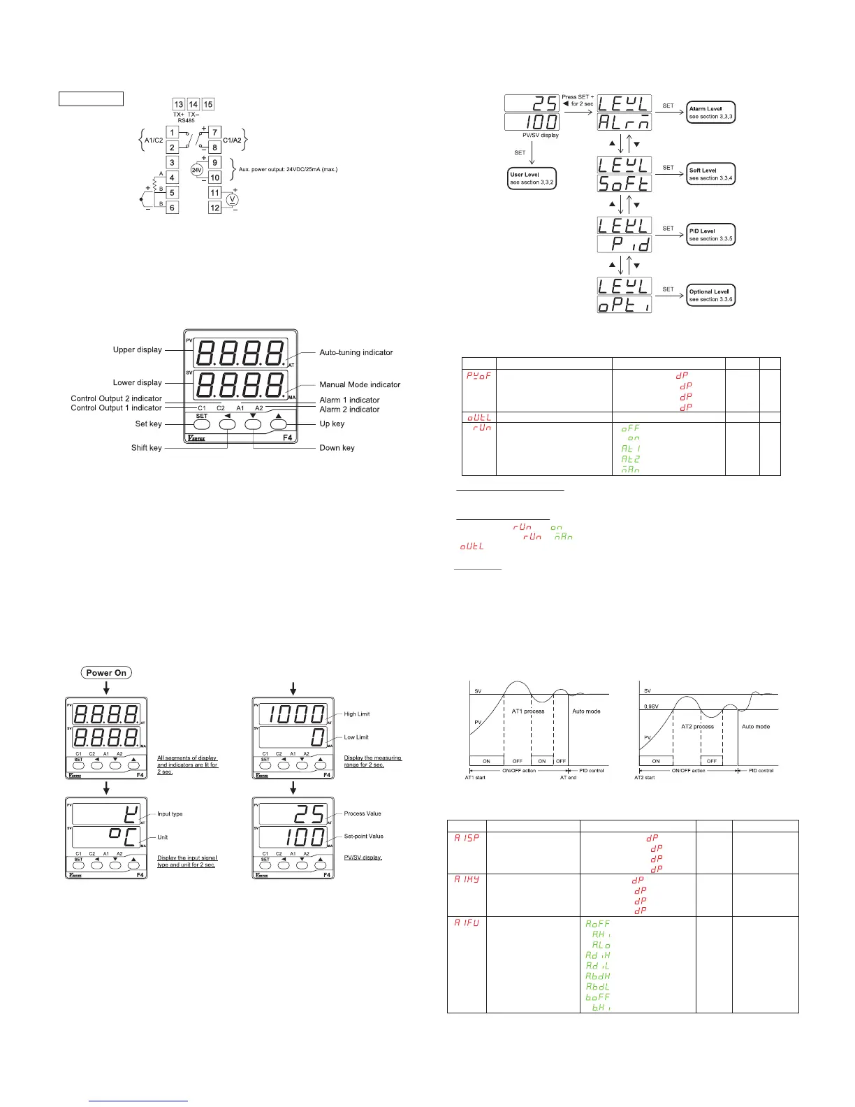
Figure 5. Menu flowchart
3.3.2.User Level
Process value offset correction
The value to be added to the PV to correct the sensor offset error.
Control output percentage
In Auto mode ( = ), it shows the percentage of power applied to the control output.
In Manual mode ( = ), the upper display will show the process value (PV) and
“ ” alternately and the “MA” indicator is lit. The value of percentage can be changed manually.
Control mode
Select the control mode to be
Off – Standby mode. Both control output and alarm are turned off.
On – Auto mode (closed loop control). In this mode, the control output percentage is determined
by PID algorithm or ON/OFF action.
AT1 – Auto-tuning mode 1. In this mode, the controller will tune the PID parameters automatically
at SV. The process will oscillate around the SV during AT1 process (Figure 6). Use AT2
mode if overshooting beyond the normal process is likely to cause damage.
AT2 – Auto-tuning mode 2. In this mode, the controller will tune the PID parameters automatically
at (SV-10%). The process will oscillate around (SV-10%) during AT2 process (Figure 6).
Man – Manual mode (open loop control). In this mode, the control output can be set manually.
Figure 6. Auto-tuning Process
3.3.3.Alarm Level
Display Description
Alarm 1 set-point
Alarm 1 hysteresis
Alarm 1 function
Range
-1999~9999 ( =0000)
-199.9~999.9 ( =000.0)
-19.99~99.99 ( =00.00)
-1.999~9.999 ( =0.000)
0~9999 ( =0000)
0~999.9 ( =000.0)
0~99.99 ( =00.00)
0~9.999 ( =0.000)
Default
10
0
Unit
unit
unit
DC power supply
Figure 2. Terminal connections
Wiring precaution:
Inverter, mechanical contact relays, arc welders, and ignition transformers are all common sources
of electrical noise in an industrial environment, so always keep signal wires away from those
noise-generating devices.
3.Operation
3.1.Front panel description
Figure 3. Front panel description
■ PV ( Upper display ) : Display the process Value, parameter index code or error code
■ SV ( Lower display ) : Display the set point value or the set value of parameter
■ C1 : Control output 1 indicator
■ C2 : Control output 2 indicator
■ A1 : Alarm 1 indicator
■ A2 : Alarm 2 indicator
■ AT : Auto-tuning indicator (The right-most decimal point of upper display)
■ MA : Manual mode indicator (The right-most decimal point of lower display)
Keypad description
■ SET key : Use to menus navigation and set value registration
■ Shift key : Shift the digit of numeral
■ Down key : Decreases the parameter value or change the setting
■ Up key : Increases the parameter value or change the setting
■ SET + Shift key for 2 sec. : Enter set up mode
■ SET + up key : Return to PV/SV display
■ Shift + Down key on powering up : set all parameters to default setting
3.2.Powering up procedure
Figure 4. Powering up procedure
3.3.Configuration
3.3.1.Menu Flowchart
After powering up procedure, the controller stays in PV/SV display. The upper display shows the
process value (measuring value) and the lower display shows the set point value (target value). All
the configurable parameters are located in different levels and can be accessed by keypad
operation as shown in figure 5.
Display Description
Process value offset correction
Control output percentage
Control mode
Range
-1000~1000 ( =0000)
-100.0~100.0 ( =000.0)
-10.00~10.00 ( =00.00)
-1.000~1.000 ( =0.000)
0.0~100.0%
: Off
: On
: AT1
: AT2
: Man
Default
0
N/A
On
Unit
Unit
%
N/A
Control output 1 (can be converted to 2nd Alarm)
Relay output : 5A/240Vac (Resistive load)
Pulsed Voltage output : DC 0/24V (Resistive load 1.2K ohms Min.)
Current output : 4~20mA (Resistive load 600 ohms Max.)
Voltage output : 0~10V ( Resistive load 600 ohms Min.)
Relay output :
5A/240Vac (Resistive load)
Alarm 1 output
(can be converted to 2nd output)
DC24V
: A.oFF
: A.Hi
: A.Lo
: A.diH
: A.diL
: A.bdH
: A.bdL
: b.oFF
: b.Hi
A.diH N/A
 Loading...