Hardware Setup
2-17
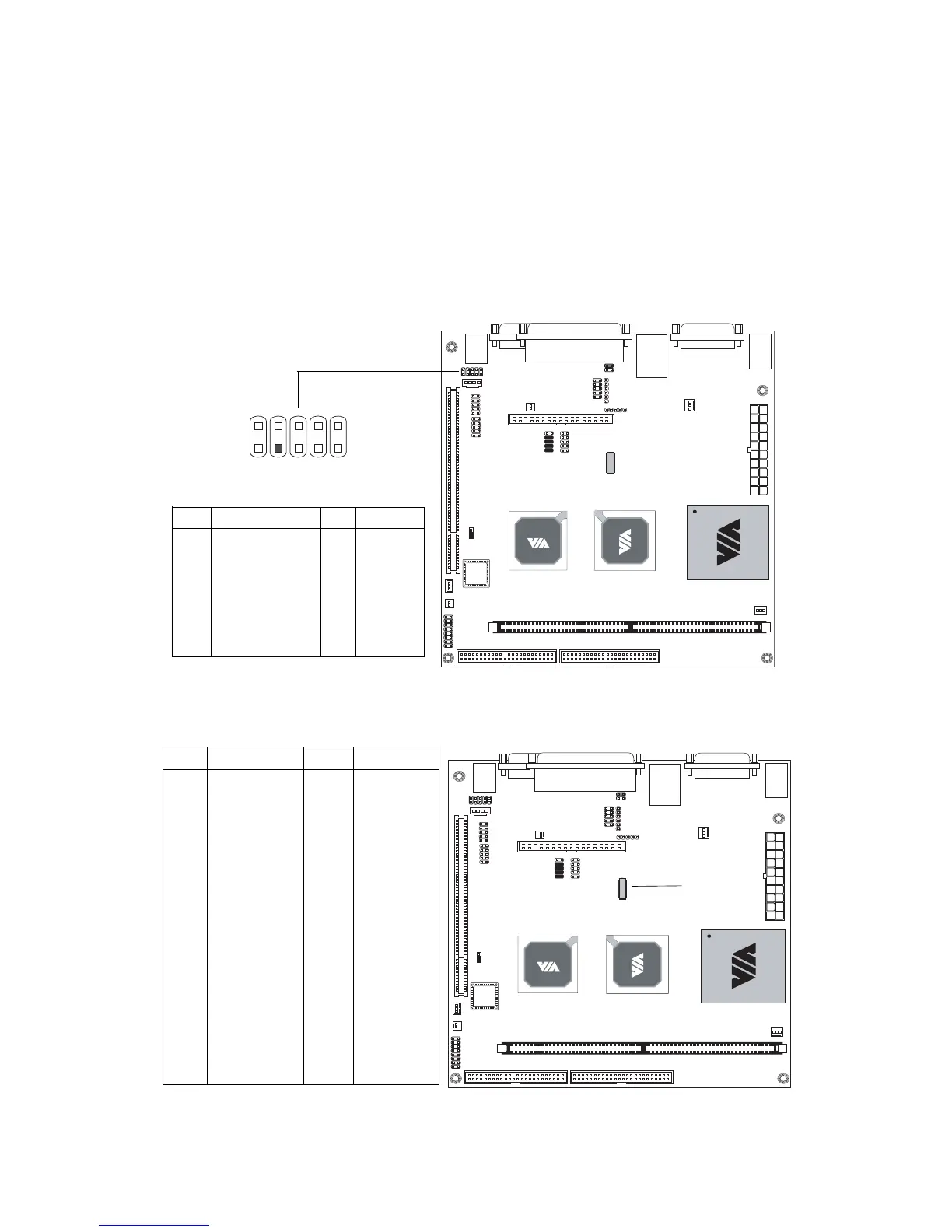
Front Audio Connector: F_Audio
This connector allows you to connect audio jacks on front panel for
convenient connection and control of audio devices. Note: 1. When the
front audio board is not in use, use the mini jumper to connect pin 5&6 and
pin 9&10 (default). 2. When the front audio board is in use, remove the
mini jumper.
PIN SIGNAL PIN SIGNAL
1 FRN_MIC 2 AGND
3 AUD_MIC_BIAS 4 +5V
5 LINE_OUT_R 6 NEXT_R
7 NC 8 Key Pin
9 LINE_OUT_L 10 NEXT_L
1
2
9
10
F_AUDIO
LVDS Module Connector: LVDS (Optional)
This connector allows you to connect to a LVDS module.
PIN SIGNAL
2 GFPD3
4 GFPD4
6 GFPD5
8 GFPCLK
10 GFPD6
12 GFPD7
14 GFPD8
16 GFPD9
18 GFPD10
20 GFPD13
22 GFPD14
24 GFPD15
26 GFPD16
28 GFPD17
30 GFPD18
32 GFPD19
34 GFPD20
36 GFPD21
38 GFPD22
40 GFPD23
PIN SIGNAL
1 GFPDE
3 GFPD0
5 GFPD1
7 GFPD2
9 GFPHS
11 GFPVS
13 GFPD11
15 GFPD12
17 ENPVDD
19 ENPVEE
21 FPBKLP
23 PWRGD_SB
25 SPCLK2
27 SPD2
29 GND
31 GND
33 3.3V
35 GND
37 5V
39 5V
LVDS
12
39
40
 Loading...