Chapter 2
12
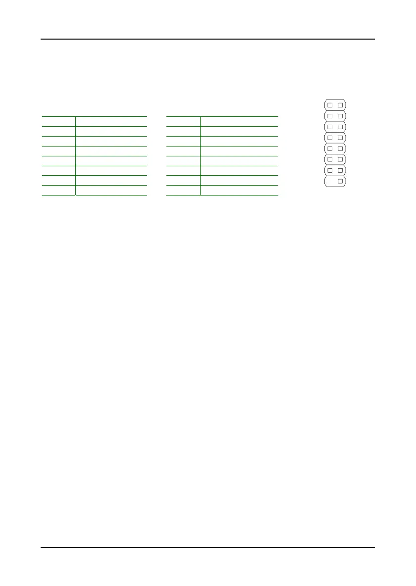
Case Connector: Front Panel
This pin header allows you to connect the power switch, reset switch, power
LED, HDD LED and the case speaker.
Pin Signal Pin Signal
1 PW_LED 2 +5V
3 PW_LED 4 HDD_LED
5 SUS_LED 6 PW_BN
7 +5V 8 GND
9 GND 10 RST_SW
11 #EXTSMI 12 GND
13 SPEAK 14 +5V
15 NC 16 #SLEEP_LED
Power Switch (PW_BN)
Connect to a 2-pin power button switch. Pressing this button will turn the
system power on or off.
Reset Switch (RST_SW)
The reset switch is used to reboot the system rather than turning the power
ON/OFF. Avoid rebooting the system, if the HDD is still working. Connect
the reset switch from the system case to this pin.
Power LED (PWR_LED)
The LED will light when the system is on. If the system is in S1 (POS - Power
On Suspend) or S3 (STR - Suspend To RAM) state, the LED will blink.
HDD LED (HD_LED)
HDD LED shows the activity of a hard disk drive. Avoid turning the power off
when the HDD LED still has a lit. Connect the HDD LED from the system case
to this pin.
Speaker (SPEAK)
The speaker from the system case is connected to this pin.
12
15 16
 Loading...