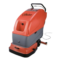
1.1 Handle.
1.2 Grab & Go Bar.
1.3 Brush Hook.
1.4 Hitchable Skirt.
1.5 Solution Tank.
1.6 Recovery Tank
1.7 Clear Dome.
1.8 Cable Restraint.
1.9 Control Panel. (See Below)
1.10 Cable Hook.
1.11 Reset Button.
1.12 Quick Change Power Cable.
1.13 Squeegee Assembly
OPERATING INSTRUCTIONS
Fill the solution tank (Fig 3) with the required amount of clean water (at a maximum of 60º C).
Add your recommended dosage of cleaning solution ensuring not to exceed a total mixture volume of
40 litres
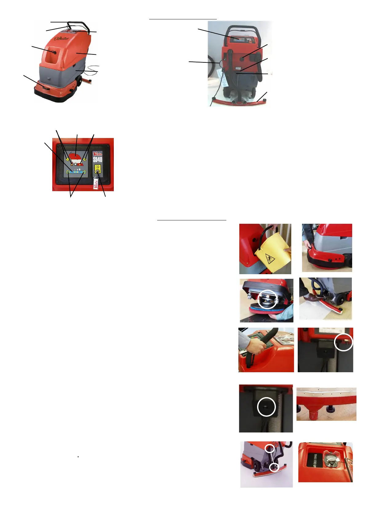
Remove the brush or drive board from the hook at the front of the machine and lift the skirt to its
raised position (Fig 4)
Tip the machine backwards to rest on the rear supports
Locate the centre of the board onto the grey locator ball and rotate the board clockwise to lock into
position. (fig 5) If at start of Brush activation, the machine appears to be unbalanced , check to en-
sure that the brush/board has been correctly fitted.
Lower the machine down (the drive board will not fully lock until the brush motor is turned on).
Lower the skirt back to the floor to act as a splash guard.
Remove the squeegee assembly from its housed position by raising and pulling backwards on the
the toe loop (Fig 6).
Adjust the squeegee pressure by tightening or loosening the knob on top of the kick bar.
Ensure that the recovery tank splash foam is inserted the correct way up (as indicated on the foam)
and is changed at a minimum of 3 monthly periods. Non-compliance can cause machine
failure and will invalidate any warranty claims made as a consequence. (Fig 12)
Plug machine into the appropriate power supply.
Switch the machine to the ON position using the Key Provided. Input required setting onto control
Panel. (See Fig 2)To operate the machine, hold onto the handle and clasp the Grab and Go bar,
pulling it upwards towards the handle. (Fig 7)
If during normal operation , the machine stops or cuts out , press and hold the reset
button for a few seconds (fig 8). The machine should the be restated in the normal manner. If the
problem persists , firstly check the brush or pad for wear or oversoiling and replace if necessary. If
the problem still persists , contact your Victor service agent
If foam appears in the clear cover of the recovery tank, drain the tank (See 18) and refill. If after
refilling , foaming continues to occur , add a defoaming agent to the recovery tank.
If prior or during operation, damage is detected on the power cable ,remove plug from the mains. The
cable can be removed from the machine by removing the attaching screw and replaced with a new
cable pack (fig 9) Also see safety information.
Monitor the Squeegee for normal wear and tear. (Fig 10)
Once a cleaning task has been completed, the following is recommended:
• The recovery and solution tanks should be drained. (See 17)
• The recovery tank should be cleaned to prevent any build up of dirt or odour. (See 18)
• The Squeegee assembly should be replaced in the park position
• The brush /board removed and placed onto its hanging hook
• The cable placed neatly onto its hook
Drain the Recovery or Solution tanks by removing the appropriate dump hose from its restraining clip
and the ball stops from the dump hose end.
NOTE:Only deposit soiled water or solution into safe, suitable , Approved locations
To assist in cleaning the Recovery Tank, (first drain it as described above and ensure there is liquid
in the Solution Tank) remove the hose from the squeegee assembly , remove the Solution Tank dump
hose from its restraining clip, remove the ball stop and attach the open ends of each hose together.
Turn vacuum on. This will suck the clean liquid from the Solution Tank and force it into the Recovery
Tank. When completed, drain the Recovery Tank. (fig 11)
Always leave the clear cover off the machine when not in use. This allows the filter to dry out and stop
moisture building up in the motor (fig 12).
1.
2.
3.
4.
5.
6.
7.
8.
9.
10.
11.
12.
13.
14.
15.
16.
17.
18
19.
Fig 12
Fig 9
Fig 6
The Control Panel (once turned on) is touch sensitive and allows the operator to select the
required operation by following the pictograms
2.1. Key Switch. - Machine power On/Off.
2.2. Vacuum On/Off Activation Pad and associated indicator Light -Depress once for
vacuum on and again for off. The indicator light will glow amber if machine is on but
Vacuum option is not in use and will go Green when option is activated.
2.3. Brush On/Off Activation Pad and associated indicator Light. - Depress once for
brush on and again for off. The indicator light will glow amber If machine is on but
brush option is not in use and will go Green when option is activated
2.4. Tank Full Light. - Indicates that the recovery tank is full and needs emptying.
2.5. Water Control. - Increase the waterflow by pressing the arrow on the right of the
panel . The waterflow will increase by one increment each time the arrow is pressed
until maximum flow is achieved. The lights beneath the water droplet pictogram will
come on to indicate waterflow levels.
2.6. Power On Indicator Light. - Indicates that , once key switched on, that power is
going to the machine.
NOTE: The vacuum motor will continue for eight seconds after the Grab and Go bar is released
to remove any excess water deposited and to prevent water travelling back through the hose
Fig 1
Fig 2
1
23
4
5
6
1
2
3
4
5
6
7
8
9
10
11
12
13
Fig 3 Fig 4
Fig 5
Fig 7
Fig 8
Fig 10
Fig 11
 Loading...