Last update:
2023-06-30 16:32
battery_compatibility:pylontech_phantom https://www.victronenergy.com/live/battery_compatibility:pylontech_phantom
https://www.victronenergy.com/live/ Printed on 2023-06-30 16:58
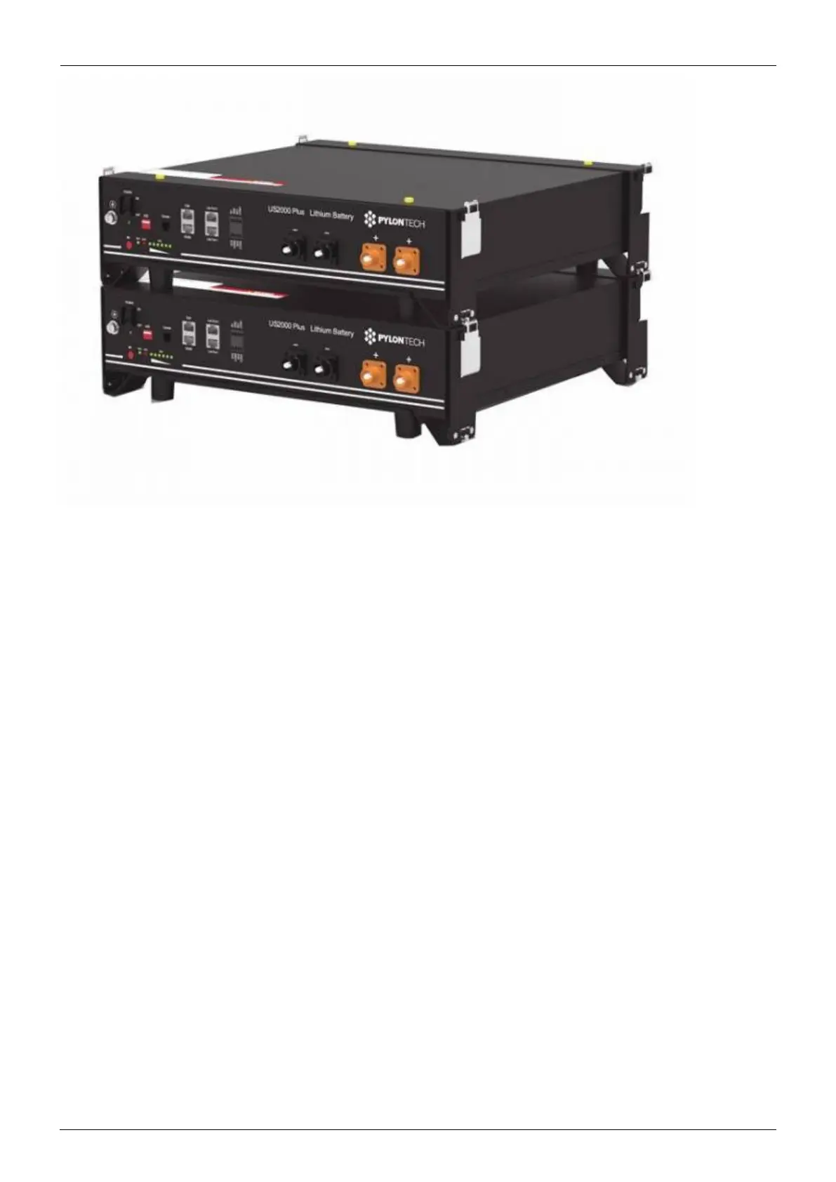
You can connect multiple battery modules together to form a single large battery by connecting the
RJ-45 cable supplied by Pylontech using the link ports on the battery. This is shown in more detail in
the example wiring diagram and Pylontech manual.
The communications for UP2500 can be paralleled up to 20 modules per string (and cannot use the
LV-HUB). Other models can connect up to 8 battery modules (see Pylontech data sheets), in those
models when using more than 8 parallel units, some limitations, additional configuration or equipment
(e.g. Pylontech LV-Hub) may apply. See your Pylontech dealer, and Pylontech documentation for more
details.
The batteries will automatically detect and link to each other, no adjustment of dip switches on the
battery module are necessary.
The battery with the empty link port 0 is the master battery.
Important note on DIP switches
No adjustment to the DIP switches is necessary, unless you are using a LV-Hub to connect a large
number of modules. The address DIP-switches must be set to 000 for correct operation, and the GX
device will not detect the battery if you use any other setting. Larger batteries using an LV-Hub is
discussed later in this document.
Type A cable
The Victron VE.Can to CAN-bus BMS type A Cable, part number ASS030710018 is used for connection
with US2000C / US3000C / UP5000 / US5000 / US5000B / Force-L.
Type B cable
The Victron VE.Can to CAN-bus BMS type B Cable, part number ASS030720018 is used for connection