56
X3.7
X3.6
C
B
A
H
D
F
G
3
3
44
3
3/N
3/N
≈
4
K
kWhkWh
5
3
(400 V~)
7
(230 V~)
X40
E
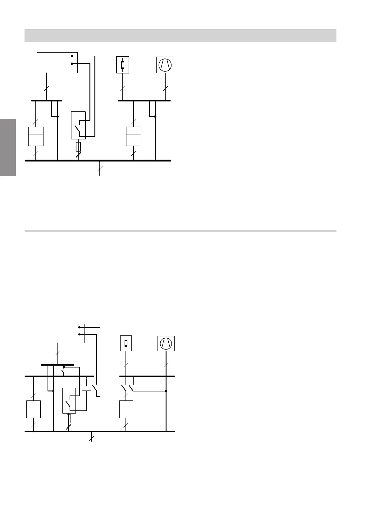
Fig. 53 Diagram excluding fuses and RCD
A
Heat pump control unit (indoor unit, luster termi-
nals: See chapter "Indoor unit: Electrical terminal
areas")
B
Instantaneous heating water heater (if installed)
C
Heat pump compressor (outdoor unit)
D
Heat pump control unit power supply: See chapter
"Heat pump control unit power supply 230 V~"
E
Premium tariff meter
F
Ripple control receiver backup fuse
G
Ripple control receiver (contact open: Power-OFF
enabled); feed: TNC system
H
Economy tariff meter
K
Feed: TNC system
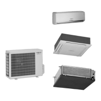
Power supply with power-OFF: With on-site load disconnect
The power-OFF signal is connected to the on-site con-
tactor of the economy tariff power supply and to the
heat pump control unit. The compressor and instanta-
neous heating water heater are "forced" off when
power-OFF is enabled.
Note
Observe the technical connection conditions of the rel-
evant power supply utility.
C
B
≈
E H
3
3
4
4
3
3/N
3/N
G
K
4
kWh
kWh
3
L
D
7
5 (400 V~)
(230 V~)
X3.7
X3.6
A
X40
F
Fig. 54 Diagram excluding fuses and RCD
A
Heat pump control unit (indoor unit, luster termi-
nals: See chapter "Indoor unit: Electrical terminal
areas")
B
Instantaneous heating water heater (if installed)
C
Heat pump compressor (outdoor unit)
D
Heat pump control unit power supply: See chapter
"Heat pump control unit power supply 230 V~"
E
Premium tariff meter
F
Ripple control receiver backup fuse
G
Ripple control receiver (contact open: Power-OFF
enabled) with backup fuse
H
Economy tariff meter
K
Feed: TNC system
L
Mains isolator
Installation sequence
Power supply (cont.)
6199592
Installation