65
Fig. 59
1.
The lever on valve
B
must be in the "left" position.
2. Open the on-site DHW supply and a DHW draw-off
point.
3. Once air stops coming out of the DHW draw-off
point, the loading cylinder is completely filled.
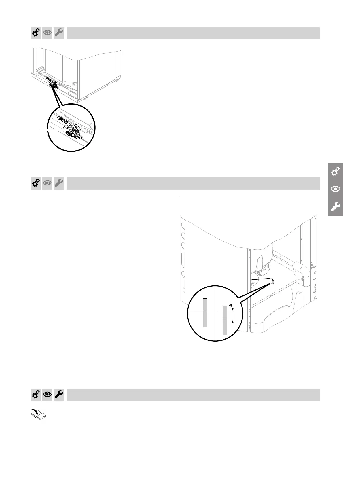
Shifting the cylinder temperature sensor for increased DHW convenience
For greater DHW convenience, the cylinder tempera-
ture sensor can be pushed into the sensor well as far
as max. 50 mm beyond the marking. Tighten the plas-
tic screw again by hand to secure it in place.
Fig. 60
A
Normal DHW convenience
B
Increased DHW convenience
Checking the expansion vessel and heating circuit pressure
Observe design information.
Heat pump technical guide
Commissioning, inspection, maintenance
Filling and venting the DHW cylinder on the DHW side
6199592
 Loading...