Activating the DC Talk Battery and Loop Current Boost
P
P
r
r
o
o
g
g
r
r
a
a
m
m
m
m
i
i
n
n
g
g
Due to the dynamic nature of the product design, the information contained in this document is subject to change without notice. Viking Electronics, and its affiliates and/or
subsidiaries assume no responsibility for errors and omissions contained in this information. Revisions of this document or new editions of it may be issued to incorporate
such changes.
Fax Back Doc 420
Printed in the U.S.A.
P
P
r
r
o
o
d
d
u
u
c
c
t
t
S
S
u
u
p
p
p
p
o
o
r
r
t
t
L
L
i
i
n
n
e
e
.
.
.
.
.
.
7
7
1
1
5
5
.
.
3
3
8
8
6
6
.
.
8
8
6
6
6
6
6
6
F
F
a
a
x
x
B
B
a
a
c
c
k
k
L
L
i
i
n
n
e
e
.
.
.
.
.
.
7
7
1
1
5
5
.
.
3
3
8
8
6
6
.
.
4
4
3
3
4
4
5
5
ZF301100 Rev B
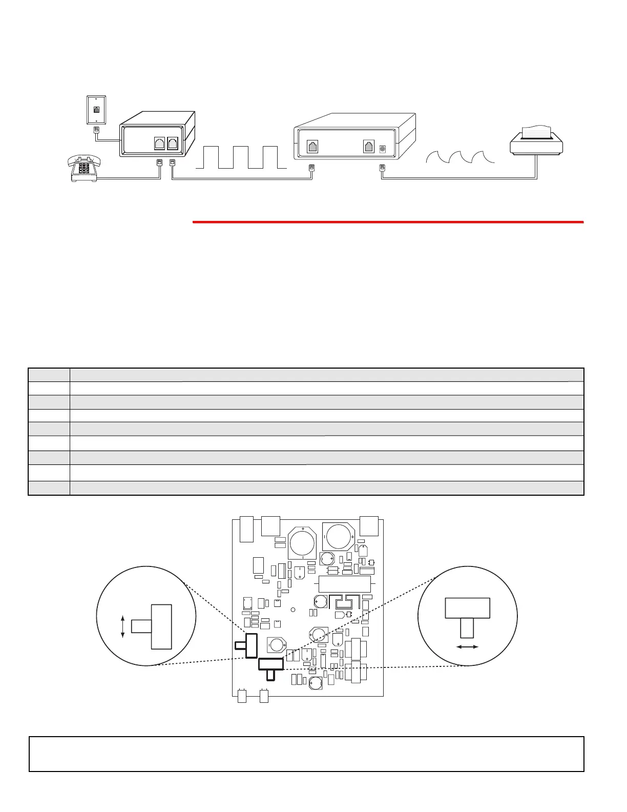
C.O. Line
Viking Electronics, Inc., Hudson, WI. 54016
D. Reshape Square Wave Ringing
Some ring generators, in equipment such as fax switches, generate square ring waves that are difficult for other
devices to detect. The RG-10A detects and converts this ring wave to a “saw tooth” shape that nearly all equipment
can detect.
The RG-10A can be configured to add loop current to low loop current lines. This feature is not compatible with systems
that regulate the loop current.
IMPORTANT: Electronic components are sensitive to static electricity. Personnel and work area should be grounded before
handling.
Note: Be very careful when performing this procedure. Only use one hard to change position of switches and only touch
the LOOP CURRENT BOOST and POLARITY switches in the RG-10A. Other components in the RG-10A can be very high
voltage if the telephone line rings while performing this procedure.
Step 1. Remove the (2) screws on the bottom of the unit and then remove the top cover.
Step 2. Connect the telephone line or analog PABX/KSU station to the LINE IN modular cord of the RG-10A.
Step 3. Connect a single line telephone (or butt set) to the OUT TO PHONES jack on the RG-10A.
Step 4. Connect power to the RG-10A.
Step 5. Set the LOOP CURRENT BOOST switch to the ON position.
Step 6. Go off hook on the single line telephone (or butt set). The LOOP LED will light and dial tone will be heard in the phone.
Step 7. Set the POLARITY switch to the position that gives you the brightest LOOP LED, while off hook with the phone.
Step 8. Replace the top cover and screws of the RG-10A.
Step 9. Reconnect the normal telephones to the OUT TO PHONES jack on the RG-10A.
 Loading...