2
4. Choosing the power supply units
Correctly size the number of power supply units for the number of installed devices. When calculating the power
supply units it is important to respect the maximum limit on permissible products for the different lines of the By-
me system.
The tables on the following pages show the absorption of the devices on the By-me BUS.
By-me power supply units
Code
Description
Draw from
Bus (mA)
Input to the
Bus (mA)
EIKON ARKÉ PLANA DIN rail
01400 Power supply unit 230V~ 29Vdc 400 mA 400
01401 Power supply unit 120-230V~ 29Vdc 1280 mA 1280
01800 SAI-BUS 29 V power supply unit - 320
01801 Power supply unit 29 V 800 mA - 800
01804 SAI-BUS By-me back-up unit - 320
01807 SAI-BUS 600 mA DIN back-up unit - 800
01830 Power supply unit 12 V - 1000
01877
By-me dimm. power supply unit LED RGB 12-24V
10 -
20580 19580 14580 Power supply unit 32 Vdc 100 mA - 100
By-me back-up unit (burglar alarm)
Code
Description
Draw from
Bus (mA)
Input to the
Bus (mA)
EIKON ARKÉ PLANA DIN rail
01804 SAI-BUS By-me back-up unit - 320
01807 SAI-BUS 600 mA DIN back-up unit - 800
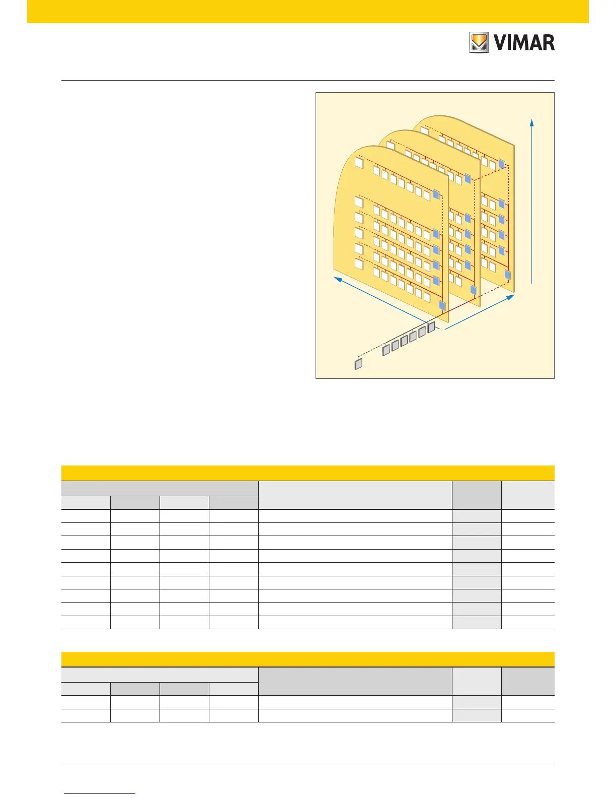
3. Areas and Lines
The system architecture offers the facility of organiz-
ing the system adopting a structure of 15 areas con-
nected to a backbone (Area 0, Line 0 dedicated to the
burglar alarm system). Each of the 15 areas can be
split up into 16 lines, each allowing the connection of
up to 128 devices. The lines are connected one with
another by way of couplers (routers) that will allow the
passage only of messages established at the time of
programming the system. Each line will be connected
to 1 or at most 2 power supply units, depending on the
demand of the devices installed.
When initializing the control unit, remember the area
and line parameters to be entered for different system
structures:
• burglar alarm branch only: Area 0 and Line 0
• automation system branch only: Area 1 and Line 0
• burglar alarm and automation system branches:
Area 0 and Line 0 (in this type of structure remember
that it is essential to immediately configure the
line coupler 01845 with Area 1 and Line 0).
4
3
64
4
3
2
1
...
0
3
4
1
2
128
15
4
3
2
1
7
6
5
128
4
3
2
1
7
6
5
AL
128
4
3
2
1
7
6
5
AL
128
4
3
2
1
7
6
5
AL
128
4
3
2
1
7
6
5
AL
127
4
3
2
1
7
6
5
AL
4
3
64
4
3
2
1
...
0
3
4
1
2
15
128
4
3
2
1
7
6
5
128
4
3
2
1
7
6
5
AL
128
4
3
2
1
7
6
5
AL
128
4
3
2
1
7
6
5
AL
128
4
3
2
1
7
6
5
AL
127
4
3
2
1
7
6
5
AL
max 128 devices
max 15 areas
Bus burglar alarm system
 Loading...