5
EN
C
B
A
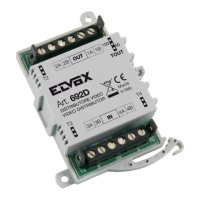
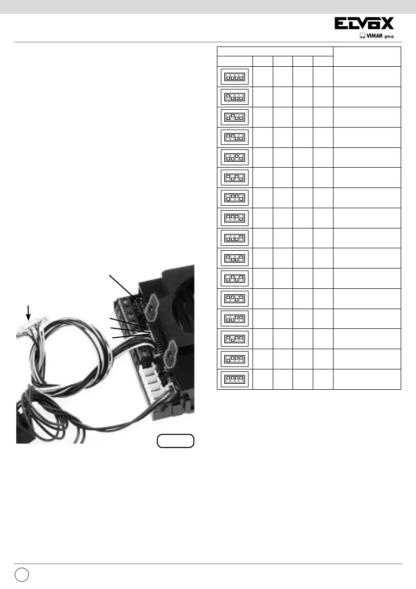
Fig. 2
CN9
ON
1234
ON
1234
ON
1234
ON
1234
ON
1234
ON
1234
ON
1234
ON
1234
ON
1234
ON
1234
ON
1234
ON
1234
ON
1234
ON
1234
ON
1234
ON
1234
1234
DIP SWITCH
ID TARGA
ON
ON
ON ON
ON
ON ON
ON ON
ON ON ON
ON
ON ON
ONON
ON ON ON
ON ON
ON ONON
ON ONON
NON ASSEGNATO
1 (MASTER)
2
3
4
5
6
7
8
9
10
11
12
13
14
15ON ONONON
SOFTWARE CONFIGURATIONS
The software congurations can be carried out in two dif-
ferent ways:
- basic conguration of software
- advanced software congurations
INSTALLATION
Assembling and installing the speech unit Art. 6931 requires
the following phases:
- installing the speech unit
- wiring the leads
- installing and wiring any additional modules
- connecting the speech unit to the system
- assigning identication
- programming the speech unit
N.B. Do not connect the bus of the speech unit to the system
until the speech unit wirings have been connected to the
entrance panel.
BUS TERMINATION
On the bottom left side, above the terminal block, there is
the 3-position connector CN9 (Fig. 2). A jumper in one of
the 3 possible positions (A, B, C) enables terminating the
bus correctly as regards the video signal for mixed systems
(audio and video door entry systems). Try out the condition
providing the best vision. If the system is solely an audio
door entry system, insert it in position A.
ASSIGNING
IDENTIFICATION
CN10 ADDITIONAL PU-
SHBUTTONS ART. 8054
ASSIGNING IDENTIFICATION
The identier is assigned with 4 dip switches on the bot-
tom left side above the terminal block (Fig. 2), outside the
enclosure and under the safety lid. The correspondence
between the position of the dip switch and the ID is speci-
ed in the following table.
MICROPHONE
ENTRANCE
PANEL ID
NOT ASSIGNED