Il manuale istruzioni è scaricabile dal
sito www.vimar.com
The instruction manual is download-
able from the site www.vimar.com
Télécharger le manuel d’instructions
sur le site www.vimar.com
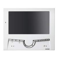
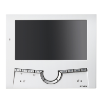
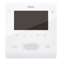
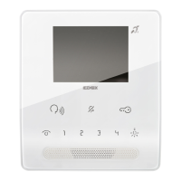
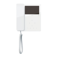
Il kit di trasformazione da tavolo art.
720A va utilizzato con monitor della
serie 7200.
- 7211 per impianti “Due Fili Elvox”
- 7214 per impianti “Digibus”
- 7200 per impianti “Sound System”
INSTALLAZIONE ART. 720A
- Estrarre la morsettiera dal fondo del
videocitofono, utilizzando un caccia
-
vite adeguato, facendo attenzione a
far leva sui due morsetti estremi e
non sulla scheda elettronica (Fig. 3).
- Eseguire il cablaggio collegando
i conduttori colorati della base da
tavolo alle morsettiere del videocito-
fono, secondo le tabelle corrispon-
denti riportate in seguito.
- Eseguire i collegamenti dell’impianto
ai morsetti della presa a muro, se-
condo gli schemi di collegamento
presenti nel manuale del videocito-
fono.
- Ricollegare la morsettiera cablata al
videocitofono assicurandosi che sia
premuta fino in fondo.
- Fissare il videocitofono alla base da
tavolo tramite le 4 viti in dotazione
(Fig. 2).
- Togliere la pellicola protettiva del
display (Fig. 2 - PartIcolare A)
- Applicare la cover frontale.
Nota: Nel caso in cui fosse necessario
togliere o sostutuire la cover frontale,
agire con un cacciavite adeguato come
illustrato in fig. 4.
Der Tischumbausatz Art. 720A wird mit
dem Monitor Serie 7200 verwendet.
- 7211 für Anlagen “Due Fili Elvox”
- 7214 für Anlagen “Digibus”
- 7200 für Anlagen “Sound System”
INSTALLATION OF TYPE 720A
- Extract the terminal block from the
bottom of the monitor, using a suita-
ble screwdriver, taking care to lever
the two end terminals and not the
circuit board (Fig. 3)
- Make the connection by wiring the
coloured conductors of the desktop
base to the terminal boards of the
monitor, according to the corre-
sponding tables shown below.
- Connect the system to the wall out-
let terminals, following the wiring
diagrams in the monitor’s manual.
- Reconnect the wired terminal block
to the monitor, ensuring that it fits
snugly
- Fit the monitor to the desk conver-
sion kit using the 4 screws supplied
(Fig. 2)
- Remove the protective film from the
display (Fig. 2 - Part A)
- Fit the front cover.
Note: If for any reason you need to re-
move or replace the front cover, use a
suitable screwdriver as shown in Fig. 4.
Desktop conversion kit type 720A must
be used with monitor series 7200.
- 7211 for “Due Fili Elvox” systems
- 7214 for “Digibus” systems
- 7200 for “Sound System” systems
INSTALLATION ART. 720A
- Extraire le bornier au fond du moni-
teur, en utilisant un tournevis appro-
prié et en faisant levier sur les deux
bornes aux extrémités et non sur la
carte électronique (Fig. 3).
- Réaliser le câblage en reliant les
conducteurs colorés de la base de
table aux borniers du portier vidéo
conformément aux tableaux cor-
respondants figurant plus avant.
Effectuer les connexions de l’instal-
lation aux bornes de la prise murale,
conformément aux schémas élec-
triques se trouvant dans le manuel
du vidéo portier.
- Reconnecter le bornier câblé au mo-
niteur en le pressant bien jusqu’au
fond.
- Fixer le moniteur à la kit de trans-
formation en version de table au
moyen des 4 vis fournies (Fig. 2).
- Enlever la pellicule de protection du
display (Fig. 2 - Pièce A)
- Appliquer la façade.
Remarque : Pour ôter ou remplacer
la façade en cas de besoin, utiliser un
tournevis approprié comme illustré sur
la fig. 4.
2
7200
720A
FRENIT
 Loading...