EasyManua.ls Logo

Vimar ELVOX Due Fili Plus K40515.M - User Manual

Vimar ELVOX Due Fili Plus K40515.M
40 pages
To Next Page IconTo Next Page
Loading...
K40515.M
Kit videocitofonico Due Fili Plus monofamiliare
Due Fili Plus one-family video door entry kit
Kit portier-vidéo Due Fili Plus pour un logement
Set Videohaustelefon Due Fili Plus für Einfamilienhäuser
Kit de videoportero Due Fili Plus unifamiliar
Kit de videoporteiro Due Fili Plus monofamiliar
Κιτ θυροτηλεόρασης μίας οικογένειας Due Fili Plus
 Due Fili Plus    
PRI
1 2
B1 B2
6922.1
POWER SUPPLY UNIT
PRI: 110-240V~ 1-0,6A 50/60Hz
1/2 B1/B2: 28V 1A CONT+0,6A INT
ESV160250
Manuale di installazione e utilizzo - Installation and operation manual
Manuel d'installation et d’utilisation - Installations- und Bedienungsanleitung
Manual de instalación y uso - Manual de instalação e utilização
Εγχειρίδιο εγκατάστασης και χρήσης -
  
Question and Answer IconNeed help?

Do you have a question about the Vimar ELVOX Due Fili Plus K40515.M and is the answer not in the manual?

Vimar ELVOX Due Fili Plus K40515.M Specifications

General IconGeneral
CategoryTelephone
ModelK40515.M
Connection2-wire
MountingWall-mounted
AudioHands-free
MaterialPlastic
ColorWhite
TechnologyDue Fili Plus
InstallationSurface
CompatibilityDue Fili Plus System

Summary

Product Kit Overview

Kit Contents and Multilingual Description

Provides a multilingual description of the K40515.M kit components and installation context.

Package Contents

Video Entryphone 40515 Details

Dimensional Data and Diagrams

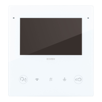
Displays physical dimensions and visual representations of the video entryphone.

Installation Guidelines

Safety Precautions

Highlights essential safety measures during device installation.

Wiring Examples

Illustrates basic connection configurations for the system.

Mounting Options

Front Panel Interface Overview

Default Button Functions

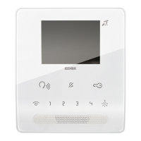
Explains the standard functions assigned to the front panel buttons.

Technical Specifications

Front Panel Components

Component Identification

Identifies and labels all parts visible on the front of the device.

Device Features and Functions

Hearing Aid Compatibility (Teleloop)

Explains the Teleloop audio frequency function for users with hearing aids.

Button Functions and Programming

Programmable Function Notes

Provides notes on how button functions can be customized via programming.

Rear Panel and Switch Table

Rear Panel Components

Identifies and labels all parts visible on the rear of the device.

Switch Table Configuration

Explains the configuration options via the DIP switch table.

DIP-Switch Configuration

Power Supply and Operation Modes

BUS POWER Switch Settings

Explains the function and settings of the BUS POWER switch.

Energy Saving Mode Operation

Describes the energy saving mode and its implications for screen behavior.

Connection Terminal Block

Terminal Descriptions

Provides a detailed explanation of each terminal's function and connection.

Initial Setup and Configuration

Language Selection

Guide for selecting the user interface language during initial setup.

Time Zone Configuration

Instructions for setting the correct time zone for the device.

Configuration Progress and Settings

Manual Date and Time Adjustment

Explains how to manually set the device's date and time.

Automatic Configuration Progress

Describes the visual feedback during the automatic configuration process.

Firmware and Software Updates

Entrance Panel (13 K1) Specifications

Dimensional Data

Physical dimensions of the entrance panel.

Technical Data

Protection grades and impact resistance ratings for the entrance panel.

Electronic Unit (13 F2.1) Specifications

Dimensional Data and Installation Notes

Physical dimensions of the electronic unit and installation advice.

Installation Examples

Surface Mounting Installation

Illustrates the process for surface mounting components.

Flush Mounting Installation

Illustrates the process for flush mounting components.

Connection Diagrams (Color Codes)

Shows wiring connections with color coding for clarity.

Installation Procedure Visual Guide

Front Panel Components Detailed

Component Identification and Descriptions

Detailed identification and description of all front panel components and controls.

Terminal Block Connections Explained

Terminal Functionality

Explains the purpose and function of each terminal on the connection block.

DIP-Switch Configuration Guide

Master;Slave ID Configuration

How to set Master/Slave IDs using DIP-switches.

Audio;Video Mode Configuration

How to configure audio/video or audio-only modes via DIP-switches.

Button and Trimmer Usage

Programming Menu Access

How to access the programming menu using buttons and trimmer.

Configurable Time Settings

Details on time settings adjustable via the trimmer.

Programming and Function Remapping

Lock Activation Time Adjustment

How to adjust the time delay for lock activation.

Conversation and Response Time Settings

How to adjust conversation and response time settings.

Button Remapping

How to remap button functions for specific actions.

Reset Function and Camera Specifications

Device Reset Procedure

Instructions on how to perform a device reset.

Camera Technical Specifications

Technical details of the integrated camera.

Power Supply Unit (6922.1) Specifications

Connection Rules and Safety Warnings

Installation Rules

Guidelines for safe and correct installation of the device.

User Warnings and Maintenance

Important warnings for users and basic maintenance advice.

Wiring Diagrams

Detailed Wiring Diagrams

Indoor Station Connection Types

Shows different connection configurations for indoor stations.

Landing Push Button Connection

Details the connection for the landing push button.

Local Power Supply Connection

Illustrates the connection for the local power supply unit.

Programmable Output Variants

Repeat Call Output Options

Explains different configurations for the repeat call output.

12 V;100 mA Output Configuration

Details the configuration for the 12V/100mA output.

Lock Control and Door Open Sensor Connections

Shows connection variants for lock control and door open sensors.

Regulatory Compliance and Safety

Normative Compliance

Lists relevant directives and standards the product complies with.

User Warnings and Maintenance

Important warnings for users and basic maintenance advice.

Additional Information and Resources

Related product manuals