15
SW24.W
Menu
The control panel programming is organised into menus
and sub-menus used to access and edit the parameters
and logics of the control panel. The control panel is
equipped with the following rst-level menus:
Menu Description
MOT Motor parameters setup
LRNT Travel calibration procedure run menu
TRV Travel parameter settings menu
OUT Auxiliary output conguration menu
IN Input conguration menu
LGC Operating logic settings menu
RAD Remote control management menu
STAT Diagnostic and reporting menu
EXP Expansion board management menu
LOAD Default value restore menu
PASS Protection level settings menu
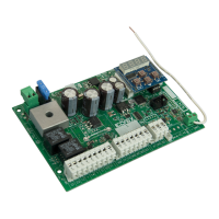
Block Terminal Description
Nominal
data
SEC
T1
Secondary transformer 24 Vac
T2
MOT
21 Opening motor 1
24 V DC
80W
22 Closing motor 1
25 Opening motor 2
24 V DC
80W
26 Closing motor 2
PS
0
Accessory power supply
negative
24 V DC
500 mA
1
Accessory power supply
positive
2
Accessories positive
checked
AUX
10 Flashing light negative
24 V DC
35 W
11 Flashing light positive
18 Electrical lock negative
12 Vdc
15 VA
19 Electrical lock positive
0 Accessories negative
500 mA
A1
Congurable auxiliary
output 1
A2
Congurable auxiliary
output 2
LSW
+E
Encoder power supply
positive
12 V DC
-E
Encoder power supply
negative
E1 Motor 1 encoder signal A
E2 Motor 1 encoder signal B
E5 Motor 2 encoder signal A
E6 Motor 2 encoder signal B
ACT
99 Common inputs
NO
C1 Congurable control 1
C2 Congurable control 2
C3 Congurable control 3
C4 Congurable control 4
SAF
99 Common inputs
NC
S1
Congurable safety de-
vice 1
S2
Congurable safety de-
vice 2
S3
Congurable safety de-
vice 3
S4
Congurable safety de-
vice 4
Using the display
The control panel settings are shown on the display and can
be edited using the menu navigation buttons as shown in
the following table:
Terminal block functions
Buttons Function
Pressing
duration
OK
Switching on the display
Sub-menu entry
Conrm value change
Instanta-
neous
▲
Scroll up
Increase parameter value
Instanta-
neous
▼
Scroll down
Reduce parameter value
Instanta-
neous
ESC
Exit the menu
Cancel value change and return
to menu
Switching o the display
Instanta-
neous
▲+▼ Resetting the card 3 s
▲+ OK Opening control 1 s
▼+ OK Closing control 1 s
ESC +
OK
Display test (switches on each
segment of the display and points
individually in sequence)
3 s
ESC +
OK
When the board is switched on
the Firmware updating mode
starts
3 s
PP Step-step control
Instanta-
neous
EN
Controllable actuators
Ref.
Description
EAM2 EKKO 300D linear operator 24 V 3 m 300 kg
EAM3 EKKO 400D linear operator 24 V 4 m 250 kg
EIM1
HIDDY 200D underground operator 24 V 2 m
200 kg
EIM2.24
HIDDY 350D underground operator 24 V 3,5 m
200 kg
 Loading...