6
d
e
b
c
a
f
a
b
7511020
FIG.3
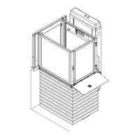
Lifting system - Fig. 3
The lifting system comprises:
- Motor (Fig. 3/a)
- Worm (Fig. 3/b)
- Nut screw (Fig. 3/c)
- Safety nut screw (Fig. 3/d)
- Control system (Fig. 3/e)
- Brake (if present) (Fig. 3/f)
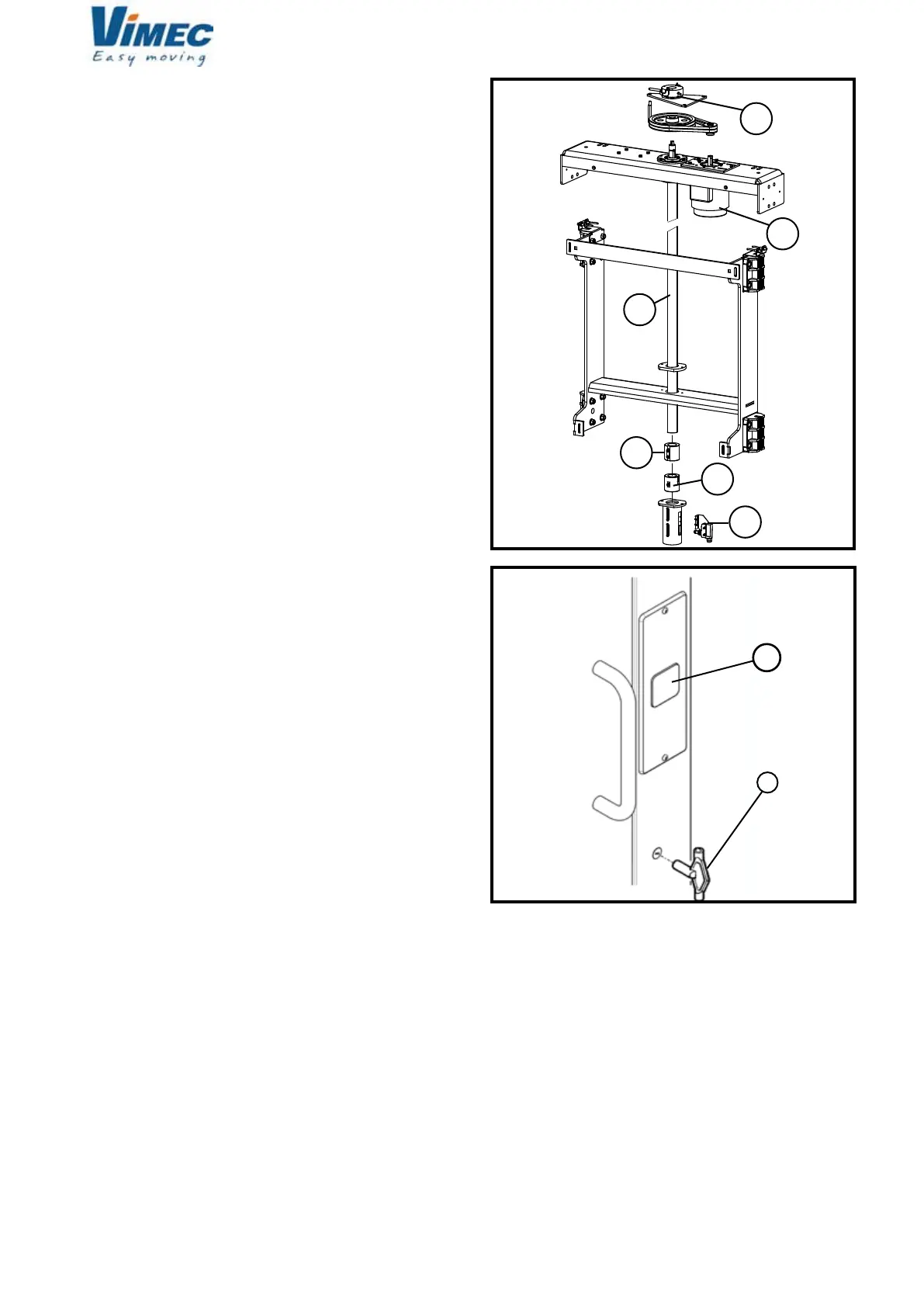
A call/send oor control containing the following devices
is provided near each oor door (if present) (Fig. 5):
- Call push button (Fig. 5/b).
This push button allows the platform to reach that de-
terminate oor enabling the entrance.
Emergency key:
In case of oor door opening in an emergency, use
the triangular re-opening key by turning it into the free
direction (Fig. 5/a).
7512020
FIG.5
 Loading...