QUESTIONS ? - COMMENTS ? - CONCERNS ?
Please do not hesitate to contact our customer service department if you have any questions, comments or concerns
regarding this or any of our products
Toll free phone (continental North America): 1-877-VINYL WK / Other calls: 905-834-5666
Email: cserv@vinylworkscanada.com / Website: www.vinylworkscanada.com
ASSEMBLY & INSTALLATION (CONTINUED)
•
Position the ladder in the pool at the desired location with the deck. Slide the ladder toward the top rail of the pool or deck (See Detail 7).
Make certain the anti-entrapment barrier does not touch the pool wall but is relatively close, reducing the gap / opening between the
barrier and the pool wall to prevent entrapment / children from swimming behind. The top platform of the ladder has 4 possible bolt holes
for securing the ladder in place. Choose the two that best suit your installation (Detail 8A&B). With a pencil, mark the location of the H2
bolts used to secure the ladder to the deck surface (See Detail 8A&B). There are also bolt slots in both ladder flanges G1 & G2. If you
do not have access to the underside of the pool deck you will have to secure the platform and the flanges using lag bolts / screws (not
provided). Drill a 5/16" hole at the marked locations. REMEMBER, use extreme caution when operating power tools around pool water
and ensure debris from drilling does not fall into pool and damage pool liner. Secure ladder in place using H2 bolts, washers and wing
nuts provided or with screws. The ladder can be secured through / to the pool top rail as well, if required (see 8B). Tighten all hardware
•
Should your pool deck surface be lower than the ladder flanges you will need to install a support block between the bottom of the
flanges and the deck surface (Detail 8B). With ladder platform level, just above the top rail, measure the distance between the deck
surface and the bottom of the mounting flanges. Cut a support block and fit between. Ensure the support block is of adequate strength
and is firming secured/fastened to the deck surface. Make certain ladder is securely fastened to the support blocks (for both flanges G1
& G2). See Detail 8B
•
Once in place and secure, ensure ladder is stable and resting on the bottom of the pool. READ OVER AND FAMILIARIZE YOURSELF
AND YOUR FAMILY, OR THOSE USING YOUR POOL, WITH THE SAFETY INSTRUCTIONS AND PROPER USE OF THIS POOL
LADDER - REMEMBER, ALWAYS SWIM SAFELY !
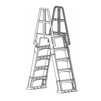
G2
A1
B1
C2
A2
D
F
C1
B2
G1
E
LADDER PARTS
DETAIL 1.1
H1
H2
H3
NUT WASHER WING NUT
#8x3/4
SCREW
HARDWARE
DETAIL 1.2
FINISHED
ASSEMBLY
DETAIL 1.3
DETAIL 1.4
HANDRAIL
SOCKET
SUPPORT
LEG
DETAIL 1.5
DECK
DECK
DECK
A B C
 Loading...