Manual VIPA System 200V Chapter 2 Hardware description
HB97E - IM - RE_253-xDPxx - Rev. 12/44 2-3
IM 253-1DP01 - DP-V1 slave - Structure
• PROFIBUS (DP-V0, DP-V1)
• PROFIBUS DP slave for max. 32 peripheral modules
(max. 16 analog modules)
• Max. 244Byte input data and 244Byte output data
• Internal diagnostic protocol
• Integrated DC 24V power supply for the peripheral modules (3.5A max.)
• Supports all PROFIBUS data transfer rates
• 1 MSAC_C1 connection (Read, Write) with 244Byte data
(4 Byte DP-V1-Header + 240Byte user data)
• 3 MSAC_C2 connections (Initiale, Read, Write, DataTransport,
Initiate Abort) with each 244Byte data
(4 Byte DP-V1-Header + 240 Byte user data)
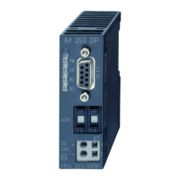
[1] LED status indicators
[2] Address selector
(Coding switch)
[3] Connector for DC 24V
power supply
[4] RS 485 interface
Front view
253-1DP01
2
1
PW
ER
RD
DE
IM 253DP
ADR.
X
2
34
VIPA 253-1DP01
+
-
1
2
DC
24V
X1
9
9
3
4
1
2
+ DC 24 V
0 V
+
-
X1
DP
RS485
5
4
3
2
1
9
8
7
6
n. c.
M24V
RxD/TxD-P (line B)
RTS
M5V
P5V
P24V
RxD/TxD-N (line A)
n.c.
1
2
3
4
5
6
7
8
9
Properties
IM 253DP
Use as
DP-V1 slave
Interfaces

 Loading...