Note: Do not tamper or remove any stickers on the VISIONTEK GL-11 POS terminal. It
may void the warranty on the unit and weaken tamper detection.
IMPORTANT SAFETY INFORMATION
To protect yourself and your VISIONTEK GL-11 POS terminal against electrical shock, fire,
power surges and other risks follow all pre-cautions while using.
INSTRUCTIONS AND CAUTIONS:
1. Never install the VISIONTEK GL-11 POS terminal in the following places:
< Exposed to direct sunlight, Moist, hot or dusty
< Unstable or vibrating places
< Near flammable liquid or gas
< Near large appliances Viz. A.C, Fridge etc.
< Near electric apparatus such as radios and TVs
< Near magnetic bodies such as audio speakers
2. Place the finger exactly on the “Scanning Area” of the finger print device
3. Avoid using the terminal during lightning storms
4. Do not use liquid or aerosol cleaners for cleaning
5. Do not disassemble or modify your GL-11 POS unit
6. Do not open the cover of the GL-11 POS terminal during operation
7. Do not expose the terminal to metal particles
8. Do not yank the power cord or place anything on the power cord
9. Do not pull the power plug with wet hands
10. Do not short or tamper with battery pack gold contact tabs during handling
11. Do not try to charge the battery on other chargers
12. Do not expose to the rain (or) water
1
Introduction
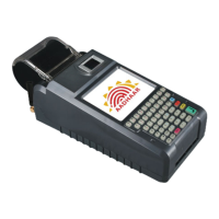
VISIONTEK GL-11 POS terminal supports finger print scanner with its hand held terminal
useful for verified biometric authentication based transactions. Based on UPek sensor with
proprietary models which can support ANSI378 and ISO19794 template formats for both
enrollment and verification along with raw image extraction. Visiontek GL-11 POS terminal
comes with seamless connectivity like GSM/GPRS class10, CDMA, Ethernet as an optional
feature.
2
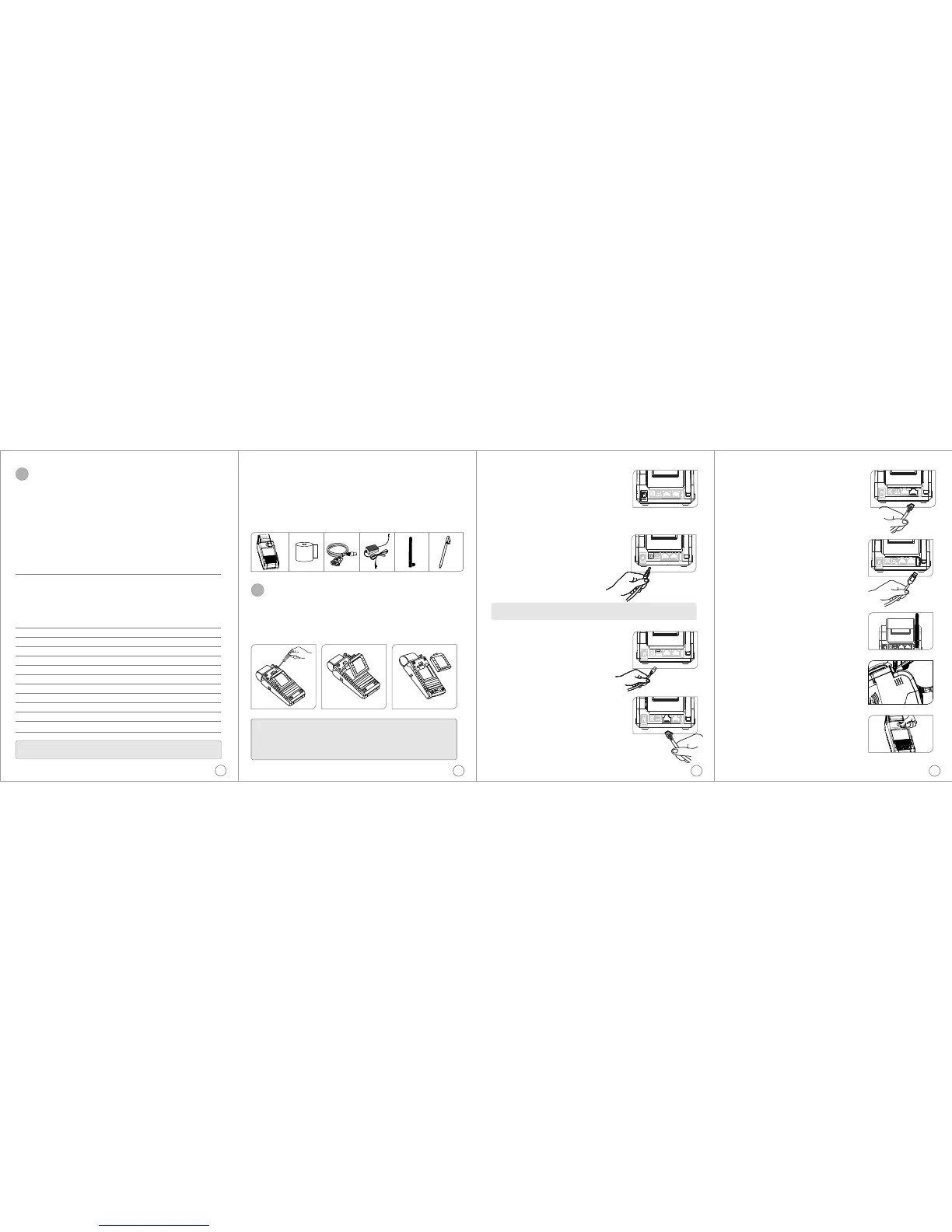
CONNECTING THE DC ADAPTOR
Insert the DC Adaptor's 9V DC output cable into the
terminal's DC power connector socket located next to the
Power Switch.
Plug the DC power adaptor's mains power plug into a
standard AC 100 - 240V, 50/60Hz DC output 9V, 2.2A
SWITCHING ON THE UNIT
Power Switch
<The power ON/OFF switch is at rear right
hand corner as shown in the figure below.
<To power up the terminal, press the ON/OFF
switch and release
<Hold the ON/OFF switch for 3 seconds to power
off the terminal.
4
CONNECTING SERIAL
INTERFACE RS-232
Insert the RJ45 cable end plug into the 8 pin
RJ45 socket marked "RS-232".
CONNECTING SERIAL
INTERFACE USB CLIENT
Insert the USB Client connector input pin into
the USB Client port of the GL-11 POS terminal.
DC Adaptor Plug and
DC Power Socket
Note: Even if the unit is not switched ON the battery pack in the unit will be charged
when ever the DC Adaptor power is available
CONTENTS OF SHIPPING CARTON
When you unpack the shipping carton, you should find:
< VISIONTEK GL-11 POS terminal with battery pack - Fig. 1a
< Thermal Paper Roll - Fig. 1b
< POS Console Cable - Fig.1c
< DC Adaptor - Fig.1d
< Stick Antenna - Fig.1e
< Stylus - Fig.1f
3
HANDLING OF BATTERY PACK
Battery removal: Open the screw on the bottom side of the battery pack and gently press the
spring latch towards the battery and lift the battery pack out of the unit.
Battery insertion: Insert the battery pack rear tabs first into the terminal then gently swing
down the spring latch end and press it into the unit and fit the screw intact.
Step 1 Step 2 Step 3
WARNING:
1. Do not dispose the battery pack in fire.
2. Dispose used batteries in accordance with local recycling regulations.
3. If for any reason you intend to remove and place aside the battery pack make sure
that the gold plated metal contacts do not come in contact with any metal objects.
4. Do not remove the battery while operation.
2
Installation
Fig.1a.
Fig.1c.Fig.1b.
Fig.1d. Fig.1e. Fig.1f.
5
CONNECTING SERIAL
INTERFACE “ETHERNET”
Insert the RJ45 cable end plug into the 8 pin
RJ45 socket marked "Ethernet”.
CONNECTING SERIAL
INTERFACE “USB HOST”
Insert the USB cable end plug into the 4 pin
USB socket marked "USB HOST”.
STICK ANTENNA
High signal gain for GSM, CDMA and Wi-Fi.
SPEAKER
Built-in speaker for audio.
FINGER PRINT SCANNER
Place the finger exactly on the “Scanning Area”
of the finger print device
 Loading...