tallation Instructions — For the Wiring and the Camera
outdoor camera is a multi-step procedure involving different power/connectivity hardware options, but it is straightforward and can be quickly learned and
The Smart Home Pro should carefully read all of these steps (and tips below) in order to ensure a successful installation and optimal performance. For additional
including detailed instructions about the Wi-Fi Bridge and PoE/PLC device setup, refer to the Field Service Smart Home Pros website. (NOTE: The procedures below
are comprehensive, meaning they cover all of the wiring as well as both the Wi-Fi Bridge and the PoE/PLC install options. Read them closely in order to fully understand each part.)
Figure-2: Wire Terminal Colors —
4931 N 300 W Provo, UT 84604
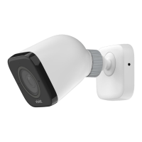
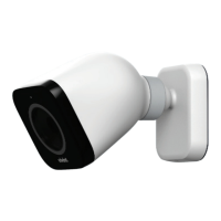
Outdoor Camera Pro (Gen 2) is a state-of-the-art high-res camera that can be added to
integrated Vivint Smart Home system in order to enhance home and perimeter security. The
provides live and recorded video that can be viewed at the control panel as well
the apps. Speaker and microphone array enable audio security features and two-way
capabilities, while the LED light ring indicates real-time camera function and status.
rofessionally installed by a Vivint Smart Home Pro, the outdoor camera features a reliable hard-
connection to the Vivint system and the home's router (for fast, smooth video) by using
-Fi Bridge or PoE/PLC device-link that supplies both power and network connectivity.
key features include: Night vision; 140° FOV (field of view); Pinch-to-zoom video image;
-triggered app notifications; Micro SD card support for on-device DVR; and speaker &
array for two-way talk via the panel or apps.
document includes a product description, installation instructions, basic operation / user
overview, as well as technical specifications and regulatory notices and declarations.
Pro (Gen 2)
S-ODC350-WHT)
Quick Reference (User Manual — Installation & Operation)
PRINT INSTRUCTIONS:
REFERENCE SHEET
FOR VS-ODC350-WHT P/N 77-600040-001 REV 1.0 |
BLACK | MATERIAL: 20 LB MEAD BOND | SIZE: 8.50" X 11.00" SCALE 1:1 |
BI-FOLD VERTICAL, BI-FOLD HORIZONTAL (TO FIT IN BOX)
To install the wiring and the camera, follow these steps:
1. Identify the best location to install the camera, consulting with the homeowner (see "Installation Tips").
Also, locate the indoor outlet where you will run the Ethernet wire and plug in either the Wi-Fi Bridge or
PoE/PLC device. IMPORTANT: The camera must be installed at least 10 feet above the ground.
2. Run Ethernet Cat5e wire from the camera to the outlet location, leaving excess wire at both ends.
3. At the outlet location (for a Wi-Fi Bridge or PoE/PLC device), to terminate the Cat5e wire:
a) Drill a hole near the outlet, and pull the wire down through the wall. IMPORTANT: Make sure to drill
and pull wire outside of the outlet box, even if it's close enough to be covered by the outlet cover plate.
b) Terminate the wire with an RJ45 jack according to the T-568B order. Strip 1" of the jacket to expose the
4 wire pairs, use the pull string to remove 2" more and cut away the jacket and string, trim the jacket
corners, untwist the wire pairs, line up the wires in the T-568B order (see Figure-1 below), cut the wires
to ¾" with a straight cut, and then slide the RJ45 jack down over the 8 wires.
c) IMPORTANT: Make sure the
orientation is correct; push the wires completely under the pins; the jacket
must be pushed under the strain-relief; securely crimp the RJ45 with the 8-pin tool.
4. At the camera mounting location, to terminate that end of the Cat5e wire:
a) Use the mounting plate to mark the location of the wiring hole, drill the hole in the home's exterior
surface, and then run the Cat5e wire through both the wall and the rubber seal on the plate.
b) Terminate the wire on the inside of the mounting plate. Strip 1.25-1.5" of the jacket to expose the 4
wire pairs, untwist each pair and arrange them over the terminal that corresponds with their color (see
Figure-2 below), use the custom punch-down tool to connect each wire to its matching terminal.
c) IMPORTANT: Do not strip wires; do not punch at an angle; inspect each terminal to ensure the wire is
completely inserted; cut off excess wire; make sure the rubber seal is tight for waterproofing.
5. Mount the camera, first attaching the mounting plate to the exterior surface with four screws (use either
#6 1" stainless steel self-drilling screws, or #6 1.25" galvanized deck screws) and anchors. (Note that you
should use a spacer if you're unable to place the mounting plate directly over the wiring hole.)
6. Attach the camera to the plate, using the T5 screw (9 mm) as a hinge rotating the camera until it snaps into
place. The pins will establish an electrical connection, supplying power once the Wi-Fi Bridge or PoE/PLC
device is connected. IMPORTANT: Make sure the wires are not powered before attaching the camera.
7. Adjust the camera to the desired angle, and then hand-tighten the ball-joint ring.
8. Add the camera to the system. With the wiring and camera installed, you should now proceed to "Adding
the Camera to the System" to finish setup and configuration, and begin using the camera.
INSTALLATION TIPS / BEST PRACTICES:
• Install within the height restrictions — 10' min. to 11' max.
• Ensure the wire is undamaged and hidden from the power
supply to the camera.
• Avoid metal outlet covers that can pinch wires inside the
Ethernet cable and cause failures over time.
• Make sure if you are mounting on an uneven surface
etc.) that the backplate does not get twisted as this will
potentially impact the pogo pin/pad connections.
• If installing under eaves/soffits, make sure to recess the
camera enough to protect it from any precipitation.
• To detach the camera, first remove the T5 screw, and then
insert a narrow, pointed tool into the release latch opening
and gently separate the camera from the plate.
Mounting Plate (inside) —
Figure-1: RJ45 Wires in T-568B Order —