This document is an installation guide for the VIVOTEK AM-520 Mounting Cap, designed for use with VIVOTEK Fixed Dome and PTZ series IP surveillance cameras. The mounting cap facilitates the installation of compatible cameras with various accessories, including pendant pipes, wall mounts, and gooseneck mounts.
Function Description:
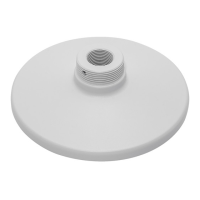
The AM-520 Mounting Cap serves as a crucial interface between VIVOTEK cameras and their mounting accessories. It provides a standardized attachment point, allowing for flexible installation options in diverse environments. The cap is designed to accommodate the routing of power and data cables, ensuring a clean and secure installation. Its primary function is to securely hold the camera in place while allowing for proper orientation and cable management. The mounting cap itself features a threaded exterior (3/4" NPT / M6) for connection to poles and various mounting brackets.
Important Technical Specifications:
- Dimensions: The mounting cap has a diameter of 180 mm (7.09 inches) and a height of 52.2 mm (2.06 inches) from the base to the top of the threaded section. The threaded section itself is 17 mm (0.67 inches) high.
- Mounting Thread: The exterior features a 3/4" NPT / M6 thread, indicating compatibility with standard piping and mounting hardware.
- Material: While not explicitly stated, the presence of various screw types (M5X10, M4X12, M3X6, M3X8) and the robust appearance suggest durable construction suitable for outdoor or demanding environments.
- Compatibility: The AM-520 is compatible with a wide range of VIVOTEK Fixed Dome and Fisheye series cameras.
- Fixed Dome Series: FD8361, FD8361L, FD8362, FD8362E, FD8363, FD8335H, FD8372, FD8162, FD8135H, FD8163, FD8131V, FD8133V, FD8134V, MD7530, MD7560, MD8562, FD8164, FD8137H, FD8131, FD8133, FD8134, F8173, FD8164V, FD8137HV, FD8167, FD8167-T, FD8138-H, FD8367-V, FD8367-TV, FD8338-HV.
- Fisheye Series: FE8172V, FE8171V, FE8174, FE8174V, FE8181, FE8181V, FE9181-H, FE9182-H, FE9381-EHV, FE9382-EHV, FE9191, FE9391-EV, FE9582-EHNV.
- Included Hardware: The mounting cap comes with various screws for camera attachment: M5X10 (4 pcs), M4X12 (3 pcs), M3X6 (3 pcs for C/E/F/K holes, 2 pcs for H holes), M3X8 (3 pcs for D/L/J holes, 4 pcs for I holes), and a hex wrench with a hex socket screw.
- Supported Accessories:
- Pendant Pipe Configurations: AM-118, AM-116, AM-117, AM-522, and a 3/4" Female adapter (separately purchased) for connecting to a 3/4" pendant pipe.
- Wall Mount Configuration: AM-212 wall mount bracket, secured with a hex socket screw.
- Gooseneck Configuration: AM-221 gooseneck mount, secured with a hex socket screw.
Usage Features:
- Versatile Mounting Options: The AM-520 supports multiple installation scenarios, including pendant (ceiling), wall, and gooseneck mounts, providing flexibility for camera placement.
- Cable Management: The design incorporates provisions for routing power lines and other cables through the mounting cap and associated accessories, ensuring a neat and protected installation. This is particularly important for cameras with cable glands, where careful routing through pendant pipes is required.
- Pre-installation Cable Routing: Users are instructed to route cables through other accessories before installing cameras to the mounting cap, simplifying the overall installation process.
- Camera Orientation: The installation guide emphasizes the importance of orienting the mounting cap correctly to achieve the desired camera shooting direction. The hex wrench and hex socket screw are used to secure the cap in its final orientation.
- Secure Attachment: Various screw types and hole patterns are provided to ensure a secure and stable attachment of different camera models to the mounting cap. The guide includes a detailed table mapping camera models to specific mounting holes and screw types.
- RJ-45 Coupler Integration: For certain camera models (e.g., FD8134), the mounting cap design allows for the integration of an RJ-45 coupler and associated cables within a recess, maintaining a compact and protected connection.
- Step-by-Step Installation: The guide provides clear, illustrated instructions for installing cameras to the mounting cap and then attaching the cap to various accessories. This includes specific steps for securing screws, routing cables, and performing initial setup.
Maintenance Features:
- Accessibility for Adjustment: The design allows for the removal, rotation, and re-installation of the mounting cap to adjust the camera's shooting direction, facilitating post-installation adjustments if needed. The hex wrench is provided for this purpose.
- Documentation Reference: Users are directed to VIVOTEK's website for updated compatibility lists and to individual camera documentation (Quick Installation Guide) for specific cabling and configuration details, including waterproof cabling preparations. This ensures that users have access to comprehensive information for both installation and ongoing maintenance.
- Screw Management: The inclusion of different screw types and a detailed screw pack description helps in organizing and identifying the correct fasteners for each camera model, simplifying assembly and potential future disassembly for maintenance.