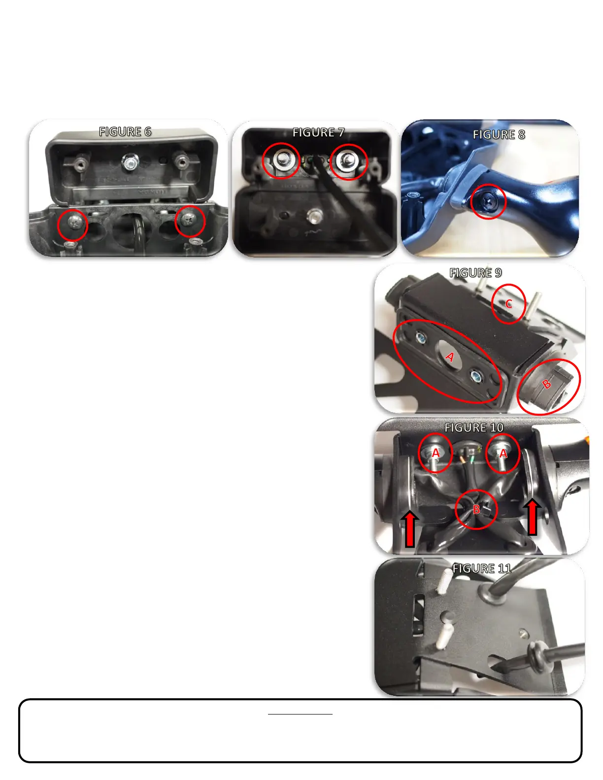
7. Remove the license plate light assembly from the OEM rear fender (2X Phillips head screws, FIGURE 6). Pull light assembly and wire
harness through the hole in the fender and set aside.
8. Remove the license plate light from the OEM plastic spacer (2X 8 mm nuts, FIGURE 7). Remove and keep the nuts, rubber gasket
and steel bushing spacers from the license plate light as they will all be reused.
9. Remove the right and left turn signals from the OEM fender (Phillips head screw, FIGURE 8). Remove turn signal body, steel
mounting bracket, screw, and the rubber base grommet as they will all be reused.
10. Begin assembly of the fender eliminator by installing the license plate light OEM
rubber gasket and bushings (FUGURE 9A), turn signal base grommets (FIGURE 9B),
and the supplied cable tie mount in the hole in the fender eliminator (FIGURE 9C).
11. Install right (blue connector) and left (orange connector) turn signals into fender
eliminator using the supplied silver metal spacers in between the steel mounting
bracket and the base grommet (FIGURE 10 arrow). Make sure the spacer is sitting
flush with the grommet perimeter before tightening the turn signal mount screws.
12. Install the license plate light with the factory lock nuts (8mm socket and wrench
required, FIGURE 10A). Tighten until the nuts bottom out on the mount bushings
and the light is firmly seated on it gasket.
13. Use the supplied cable tie to secure the three wiring looms to the cable tie mount
(FIGURE 10B). Route the wiring looms in an “X” shaped through the cable tie and
then through the two oval slots in the fender eliminator. The blue connector will
go through the hole nearest the right turn signal, and the other two wiring looms
will go through the other slot (FIGURE 11). Trim the cable tie flush after tightening.
14. Thread the electrical connectors through the two supplied grommets and pull the
grommets over the wiring looms toward the fender eliminator. Install the
grommets into the fender eliminator body by pushing the groove of the grommet
into the slots on the fender eliminator (FIGURE 11).
15. Install the assembled fender eliminator on the motorcycle. Use the supplied
aluminum spacers on the two threaded studs between the fender eliminator and
undertail. Start by threading all the electrical connectors through the two holes in
the plastic undertail and then line up the two threaded studs on the fender
eliminator with the holes on the motorcycle subframe. Secure the fender
eliminator to the motorcycle with the supplied flanged nuts. Use one of the factory
fender bolts from Step 4 in the front threaded insert of the fender eliminator.
16. Route the wiring looms in the factory manner, and use the reusable cable to
secure a service loop of the excess wiring. Reconnect the three connectors.
17. Re-install rear seat and install the license plate with the original dealer-supplied
hardware. Perform a system test to ensure all lights are functional and double
check that all hardware is tight before riding the motorcycle.
TERMS & CONDITIONS
Legal Notice: The purchaser and/or user of any Vagabond Motorsports, LLC branded parts releases Vagabond Motorsports, LLC from all liabilities pertaining to use of the parts. The user
acknowledges that any modification, alteration or change to a motorized vehicle may increase the risk of accident and/or injury. Additionally, the user acknowledges any change may render
the motorized vehicle illegal for use in public roads. Warranties: All Vagabond Motorsports, LLC branded products carry a one-year limited liability against workmanship and material defects.
This Warranty is provided to the original purchaser of the products. Return Policy: All approved returns must be in new and unused condition within 90 days of purchase.
 Loading...