22
DPLL
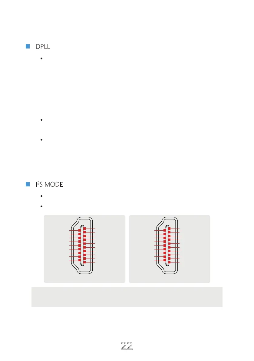
Note: This option is used to match different I
2
S interface standards, please
check the interface definition of the signal source before use.
I
2
S MODE
NORMAL
REVERSED
NORMAL
I
2
S DATA +
I
2
S DATA -
I
2
S LRCLK +
I
2
S LRCLK -
GND
NC
DSD FLAG
NC
GND
GND
GND
GND
I
2
S MCLK +
I
2
S MCLK -
NC
MUTE
NC
I
2
S BCK +
I
2
S BCK -
2
1
18
19
REVERSED
GND
GND
I
2
S MCLK +
I
2
S MCLK -
NC
MUTE
NC
I
2
S BCK +
I
2
S BCK -
I
2
S DATA -
I
2
S DATA +
I
2
S LRCLK -
I
2
S LRCLK +
GND
NC
DSD FLAG
NC
GND
GND
2
1
18
19
MIN ~ MAX
(A total of 15 kinds, the default is 7 kinds. The larger the number is, the stronger the range
to adapt to jitter, and the smaller the number, the better the performance against clock jitter.)
This DPLL setting is a special function of ESS series products. It can adjust the internal
DPLL digital phase locked loop circuit Bandwidth, so that the chip achieves a balance
between anti clock jitter and input tolerance.
Its function:
When the clock stability of the input signal is good, this value can be reduced,
so that the clock performance of the system is better;
When the clock stability of the input signal is not good, the sound may be inter-
rupted. Increase this value can avoid the sound interruption! Especially when
using TV as signal source!
 Loading...