Do you have a question about the Voith TN Series and is the answer not in the manual?
Explains the basic working principle of the turbo coupling.
Details the structure and meaning of the product's type designation.
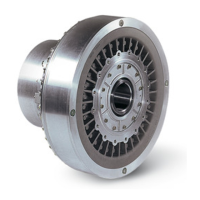
Illustrates different constructional types and their configurations.
Shows examples of input-side connecting couplings for various types.
Shows examples of output-side connecting couplings for various types.
Specifies tightening torques for set screws and fixing bolts.
Specifies tightening torques for plugs, glasses, and screws.
Details tightening torques for various types of fastening screws.
Declares the product's status as an assembly, not a machine.
Declares conformity with relevant EU directives and standards.
Explains safety message structure, danger words, symbols, and their meanings.
Defines proper use and describes unintended uses of the turbo coupling.
Covers risks from structural modifications, general dangerous situations, hot surfaces, rotating parts, and noise.
Addresses risks from electric shock, static, overspeed, ambient temperatures, and fluid leaks.
Details risks related to fire, slipping, and explosive atmospheres.
Provides guidance on remaining risks, accident procedures, and operational information.
Describes how the turbo coupling is delivered and packaged.
Lists the components included in the delivery scope.
Provides guidelines and warnings for transporting the turbo coupling.
Details procedures and safety precautions for lifting the turbo coupling.
Explains storage conditions, packing, and preservation methods.
Lists the necessary tools and measuring equipment for installation.
Outlines preparatory steps before installation, including checks and cleaning.
Describes requirements and marking for keys used in shaft-hub connections.
Details the procedure for mounting the basic type T turbo coupling.
Details the procedure for mounting the basic type T turbo coupling.
Outlines the procedure for mounting the basic type TN turbo coupling.
Outlines the procedure for mounting the basic type TN turbo coupling.
Covers alignment procedures and related topics.
Lists available input-side connecting couplings for type T.
Lists available output-side connecting couplings for type TN.
Provides laid lengths and type matching for couplings.
Specifies permissible radial and axial displacement values.
Describes methods for performing alignment using laser or dial gauges.
Lists requirements for mineral oil as an operating fluid.
Lists specific types of mineral oils suitable for use.
Recommends operating fluids for special applications like food industry.
Lists requirements for water as an operating fluid.
States that drinking water usually meets requirements.
Details water usage with centrifugal valves and required grease amounts.
Provides instructions on filling the turbo coupling with operating fluid.
Guides filling for horizontal installations.
Guides filling for vertical installations.
Describes procedures for checking the operating fluid level.
Describes how to check fluid level in horizontal installations.
Describes how to check fluid level in vertical installations.
Provides procedures for draining the operating fluid.
Procedure for draining without a delay chamber.
Procedure for draining with a delay chamber.
Procedure for draining in vertical installations.
Outlines periodic maintenance tasks and intervals.
Provides instructions for cleaning the exterior of the turbo coupling.
Covers maintenance of flexible connecting couplings.
Details how to check the flexible element for wear.
Specifies maintenance intervals for flexible elements based on wear.
Covers bearing lubrication and maintenance.
Guidance on bearing lubrication with mineral oil.
Guidance on bearing lubrication with water.
Instructions for replacing or re-lubricating bearings.
Explains the function and identification of fusible plugs.
Specific guidance for fusible plugs in non-Ex applications.
Specific guidance for fusible plugs in Ex applications.
Form to document assembly checks and measurements.
Form to document commissioning procedures and checks.
Form to document general maintenance activities.
Form to document maintenance of flexible connecting couplings.
Outlines preparatory steps and safety for disassembly.
Details the procedure for disassembling the basic type T turbo coupling.
Procedure for disassembly using a hydraulic removal device.
Procedure for disassembly using a mechanical removal device.
Refers to Chapter 8.3 for reassembly.
Refers to Chapter 8.4 for disassembly.
Refers to Chapter 8.4 for reassembly.
Describes the MTS unit for temperature pre-warning.
Covers BTS non-contacting thermal switch units.
Describes the BTS unit for temperature pre-warning.
Describes the BTS-Ex unit for limiting max surface temperature.
Describes the BTS non-contacting thermal measuring device.
Provides an overview of components for specific turbo coupling models.
Lists spare parts for turbo coupling models 154-274.
Lists spare parts for turbo coupling models 366-1150.
Lists spare parts for connecting couplings.
Lists spare parts for input-side connecting couplings.
Lists spare parts for output-side connecting couplings.
| Brand | Voith |
|---|---|
| Model | TN Series |
| Category | Industrial Equipment |
| Language | English |