42
7Max/Min
Here, the automatic display of the min and max measured values during measurement can be switched on or off.
Pushing the button “Enter” actuates the slider in the display.
I = enabled, o = disabled
8Average/Dif
Here, the automatic display of the average and difference from min and max measured values during measurement
can be switched on or off. Pushing the button “Enter” actuates the slider in the display.
I = enabled, o = disabled
9Ambient Temp/RH
Here, the automatic display of the ambient temperature and relative humidity can be switched on or off. Pushing the
button “Enter” actuates the slider in the display.
I = enabled, o = disabled
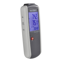
The sensors for ambient temperature and relative humidity are installed in the meter (14). Observe the de-
layed measurement by the constructional placement of the sensors. Give the meter enough time to adjust
to the ambient conditions (approx. 30 minutes for a stable measured value).
10Dew point/Wetbulb
Here, the automatic display of the dew point and the evaporation temperature (WetBulb) can be switched on or off.
Pushing the button “Enter” actuates the slider in the display.
I = enabled, o = disabled
The dew point and the evaporation temperature are calculated values that result from the IR surface
temperature, the ambient temperature and the relative humidity. The sensors for ambient temperature and
relative humidity are installed in the meter (14). Observe the delayed measurement by the constructional
placement of the sensors. Give the meter enough time to adjust to the ambient conditions (approx. 30
minutes for a stable measured value).
11Type-K
Here, the automatic display of an external type K thermocouple sensor can be switched on or off. Pushing the button
“Enter” actuates the slider in the display.
I = enabled, o = disabled
When this function is activated, the thermocouple socket (15) is monitored. Once an external type K thermo
sensor is connected, the contact temperature appears in the display during the measurement as well. If no
sensor is connected, this function is automatically concealed.
12Colour
Here, the number colour of the displayed parameters can be set. In the lower line, the RGB colour values are dis-
played for information.
Possible set values are:
White, black, red, yellow, blue, green
 Loading...