Do you have a question about the Vortec 610 and is the answer not in the manual?
Warning about compressed air causing death, blindness, or injury and safety precautions.
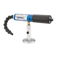
Description of the Vortec Cold Air Gun, its function, and applications.
Details on filtering, sizing, and temperature requirements for compressed air supply.
Diagram and description of the adjustable cold air gun assembly components.
How to regulate temperature and volume using the adjustment knob.
Guidance on maintaining the Cold Air Gun, including cleaning and reassembly.
Solutions for insufficient airflow, including line size, pressure, and blockages.
Information on Vortec's limited warranty for compressed air products.
The Adjustable Cold Air Gun is a device designed to convert filtered, 100 psig (6.9 Bar) compressed air into a cold airstream. This product is suitable for a wide range of industrial spot cooling and dry machining applications.
The manual covers the following models, including their BSP versions:
The primary function of the Cold Air Gun is to provide adjustable cold air for various industrial applications. It operates by taking compressed air and transforming it into a cold air stream, which can be regulated in terms of temperature and volume.
Temperature and Volume Regulation: The temperature and volume of the cold air stream are controlled by an adjustment knob located at the back of the gun.
Optimal Cooling Capacity: Maximum cooling capacity is achieved when there is a balance between the cold air volume and the cold air temperature drop. This means an adequate volume of cold air at a reasonable cold temperature is required for the maximum cooling effect. In normal operation, this balance typically occurs when the adjustment knob is turned 1/4 to 3/8 open (counterclockwise) from the full closed (clockwise) position.
Compressed Air Consumption: The Adjustable Cold Air Gun consumes between 15-35 SCFM (425-990 SLPM) of compressed air.
Operating Pressure and Temperature Limits:
Filter Recommendations: A 5 micron or smaller filter is required to remove water and dirt from the compressed air supply. Failure to use a filter can lead to clogging and freezing of the compressed air paths within the Vortec product. Filter elements must be changed regularly, with frequency depending on the condition of the compressed air supply. Filters should be installed as close as possible to the Vortec product in the supply line.
Filter and Replacement Part Item Numbers: The manual provides a detailed table for filter and replacement part item numbers based on the Vortec model:
| Vortec Model | 5 micron Air Filter | Oil Removal Filter | Single Outlet Flex Nozzle | Magnetic Mounting Base | Replacement Generator Kits (5 pcs) |
|---|---|---|---|---|---|
| 610, 612 | 701S-24A | 701S-48 | 606-FN | 208GK-15H | |
| 610-1, 612-1 | 701S-24A | 701S-48 | 606-FN | 620-26 | 208GK-15H |
| 620, 622 | 701S-24A | 701S-48 | 606-FN | 208GK-25H | |
| 620-1, 622-1 | 701S-24A | 701S-48 | 606-FN | 620-26 | 208GK-25H |
| 630, 632 | 701S-36A | 701S-54 | 606-FN | 208GK-35H | |
| 630-1, 632-1 | 701S-36A | 701S-54 | 606-FN | 620-26 | 208GK-35H |
Compressed Air Line Sizing: The manual includes tables to help determine the appropriate compressed air line size for optimal performance. Users need to calculate total product compressed air consumption (SCFM, SLPM), determine the length of the compressed air line, and then use the tables to find the recommended pipe size.
Maximum Airflow (SCFM) Through Pipe at 5 PSIG Pressure Drop (100 PSIG and 70°F):
| Pipe Length (Feet) | 1/4 | 3/8 | 1/2 | 3/4 | 1 | 1-1/4 | 1-1/2 | 2 | 2-1/2 |
|---|---|---|---|---|---|---|---|---|---|
| 10 | 29 | 65 | 120 | 254 | 480 | 978 | 1483 | 2863 | 4536 |
| 20 | 21 | 46 | 85 | 180 | 340 | 692 | 1049 | 2024 | 3208 |
| 30 | 17 | 37 | 70 | 147 | 277 | 565 | 856 | 1653 | 2619 |
| 40 | 15 | 32 | 60 | 127 | 240 | 489 | 792 | 1431 | 2268 |
| 50 | 13 | 29 | 54 | 114 | 215 | 437 | 663 | 1280 | 2029 |
| 60 | 12 | 26 | 49 | 104 | 196 | 399 | 606 | 1169 | 1852 |
| 70 | 11 | 25 | 46 | 96 | 181 | 370 | 561 | 1082 | 1715 |
| 80 | 10 | 23 | 43 | 90 | 170 | 346 | 524 | 1012 | 1604 |
| 90 | 10 | 22 | 40 | 85 | 160 | 326 | 494 | 954 | 1512 |
| 100 | 9 | 21 | 38 | 80 | 152 | 309 | 469 | 905 | 1435 |
Maximum Airflow (SLPM) Through Pipe at 0.3 Bar Pressure Drop (6.9 Bar and 21°C):
| Pipe Length (Meters) | 1/4 | 3/8 | 1/2 | 3/4 | 1 | 1-1/4 | 1-1/2 | 2 | 2-1/2 |
|---|---|---|---|---|---|---|---|---|---|
| 3 | 821 | 1840 | 3396 | 7188 | 13584 | 27677 | 42117 | 81023 | 128369 |
| 6 | 594 | 1302 | 2406 | 5094 | 9622 | 19584 | 29687 | 57279 | 90786 |
| 9 | 481 | 1047 | 1981 | 4160 | 7839 | 15990 | 24225 | 46780 | 74188 |
| 12 | 425 | 906 | 1698 | 3594 | 6792 | 13839 | 20999 | 40497 | 64184 |
| 15 | 368 | 821 | 1528 | 3226 | 6085 | 12367 | 18763 | 36224 | 57421 |
| 18 | 340 | 736 | 1387 | 2943 | 5547 | 11292 | 17150 | 33083 | 52412 |
| 21 | 311 | 708 | 1302 | 2717 | 5122 | 10471 | 15877 | 30621 | 48535 |
| 24 | 283 | 651 | 1217 | 2547 | 4811 | 9792 | 14829 | 28640 | 45393 |
| 27 | 269 | 623 | 1132 | 2406 | 4528 | 9226 | 13980 | 26998 | 42790 |
| 31 | 255 | 594 | 1075 | 2264 | 4302 | 8745 | 13273 | 25612 | 40611 |
Rubber Hose Airflow Rating:
Installation: The Cold Air Gun can be installed by directly plumbing it to an appropriately-sized hard-piped compressed air source, provided the pressure does not exceed 150 psig (10.3 Bar).
Safety Considerations:
Compressed Air Dryer: If the desired cold air stream temperature is less than 32°F (0°C), a compressed air dryer may be necessary to prevent ice formation inside the Vortec product.
No Moving Parts (Except Adjustment Knob): The Cold Air Gun is designed with minimal moving parts, primarily the adjustment knob, which simplifies maintenance. It relies on filtered compressed air for proper operation.
Cleaning: The Cold Air Gun can be disassembled for cleaning. If disassembled, the Cold Cap must be reassembled tightly to ensure the Generator seats properly against the body assembly. A loose Cold Cap will reduce cooling capacity.
Troubleshooting: The manual lists common causes for insufficient airflow and their remedies:
If issues persist, users are advised to contact Vortec for assistance.
Vortec compressed air products manufactured by ITW Air Management are covered by a ten-year warranty from the date of invoice. Products found to be defective due to manufacturing defects will be replaced or repaired. Full warranty details and limitations are available on the Vortec website. ITW Air Management disclaims any specific warranty of merchantability or fitness for a particular purpose.
| Brand | Vortec |
|---|---|
| Model | 610 |
| Category | Power Tool |
| Language | English |