- 2 -
Fig. 2: Installation at the Lateral Top Side
Installation from the top, Fig. 1:
The bore hole Ø 12.5 mm for the probe should be placed
at the topmost location and in the tank centre. The
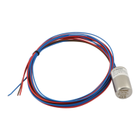
antikink device at the screwed cable gland is not required
and can be cut off. Screwed cable gland has to be bolt
together with sealing ring and counter nut.
Installation at the lateral top side, Fig. 2:
The bore hole Ø 12.05 mm for the probe should be
placed as high as possible at the tank top. The antikink
device is located at the tank. It ensures the required
distance between probe and tank wall. Thus, indication
errors due to formation of algae or soiling of probe and
tank wall are avoided. Screwed cable gland has to be
bolt together with sealing ring and counter nut.
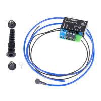
Module mounting, Fig. 1 and 2:
Drill a second bore hole Ø 9.5 mm for the rubber dowel
in the immediate vicinity of the bore for the probe. The
rubber dowel is used to install the electronics module
with the long stainless steel screw M5x30. It is
important to ensure that the probe cable lays shortest
possible route from the electronic module to the
screwed cable gland of the probe (Fig. 2 and Fig. 4) to
avoid errors.
Conductor mounting on the plastic tank, Fig. 1 and Fig. 2:
Set the hole Ø9.5 mm for the conductor as near as possible to the bottom of the plastic tank. The drilling has to be
burr. Rubber dowel with washer, cable lug and stainless steel screws M5x20 can be installed, Fig. 3
Conductor connection to the metal tank, Fig. 4:
Conductor screw and rubber dowel are not required for metal tanks. Instead, connect the cable lug electrically to the
tank by means of a Parker screw near the electronic module.
Fig. 3: Conductor with Plastic Tanks Fig. 4: Conductor with Metal Tanks
Probe Length:
Insert a screwed cable gland into the bore hole and pull up the probe until a clearance of approx. 10-20 mm is left
between the probe end and the tank bottom. Thus, indication errors due to formation of sludge in sewage water and
feces tanks is avoided. Tighten the screwed cable gland until the probe will be held perfectly, even in case of slight of
tensile load.
Shorten excess of probe cable, neatly strip the insulation and screw down to the electronic module with the terminal
"Probe".
 Loading...