www.prolight.co.uk DTM Series User Manual
4
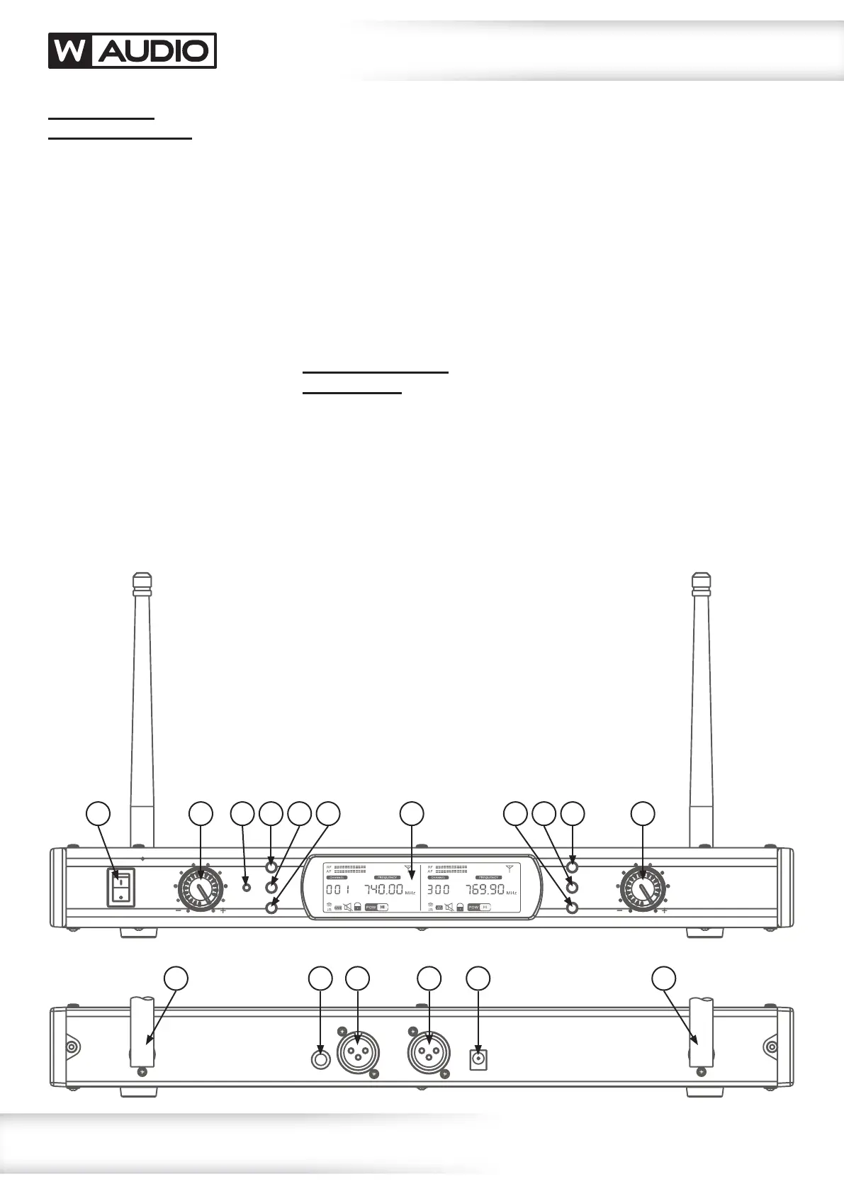
Receiver front
panel identication:
1. Power Switch
On/Off control for the system receiver
2. Volume Control – Channel A
The receivers output volume is
adjustable. Turn the level control anti
clockwise to the lowest setting, or
turn clockwise to adjust to the highest
setting. Each channel features an
independent volume control.
3. IR Transceiver
The IR transceiver is used to
communicate with the systems
transmitters during setup.
4. Up Button – Channel A
5. Set Button – Channel A
6. Down Button – Channel A
7. Display
The receiver features a backlit display
allowing the user to see information
about the receiver including frequency,
channels, mute status, audio,
RF status and battery level.
8. Down Button – Channel B
9. Set Button – Channel B
10. Up Button – Channel B
11. Volume Control – Channel B
The receiver’s output volume is
adjustable. Turn the level control anti
clockwise to the lowest setting, or
turn clockwise to adjust to the highest
setting. Each channel features an
independent volume control.
Receiver rear panel
identication:
12. Removable BNC Antenna
– Channel A
The antenna receives the RF radio
signal from the transmitter unit. For
optimum reception, orientate vertically.
Reception maybe impaired by obstacles
between the transmitter and receiver.
High power electrical equipment can
cause unwanted interference.
13. Audio (MIX) Output
6.35mm (1/4”) jack socket outputting
an unbalanced, line level audio output
featuring both audio channels.
14. Balanced Audio Output B
Individual, balanced audio outputs
via 3 pin XLR for audio channel B.
15. Balanced Audio Output A
Individual, balanced audio outputs
via 3 pin XLR for audio channel A.
16. DC Power Input
The receiver is powered by a standard
DC power input 12V DC, 1A regulated
voltage supply.
17. Removable BNC Antenna
– Channel B
The antenna receives the RF radio
signal from the transmitter unit. For
optimum reception, orientate vertically.
Reception maybe impaired by obstacles
between the transmitter and receiver.
High power electrical equipment can
cause unwanted interference.
1 2
12 14 1513 16 17
3 84 95 106 117
Operating instructions
 Loading...