5WAC Lighting retains the right to modify the design of our products at any time as part of the company's continuous improvement program. JULY, 2018
waclighting.com
Phone (800) 526.2588
Fax (800) 526.2585
Headquarters/Eastern Distribution Center
44 Harbor Park Drive
Port Washington, NY 11050
Central Distribution Center
1600 Distribution Ct
Lithia Springs, GA 30122
Western Distribution Center
1750 Archibald Avenue
Ontario, CA 91760
INSTALLATION INSTRUCTION
Volta 4.5” LED - Adjustable Round Trim
R4RAT, R4RAL
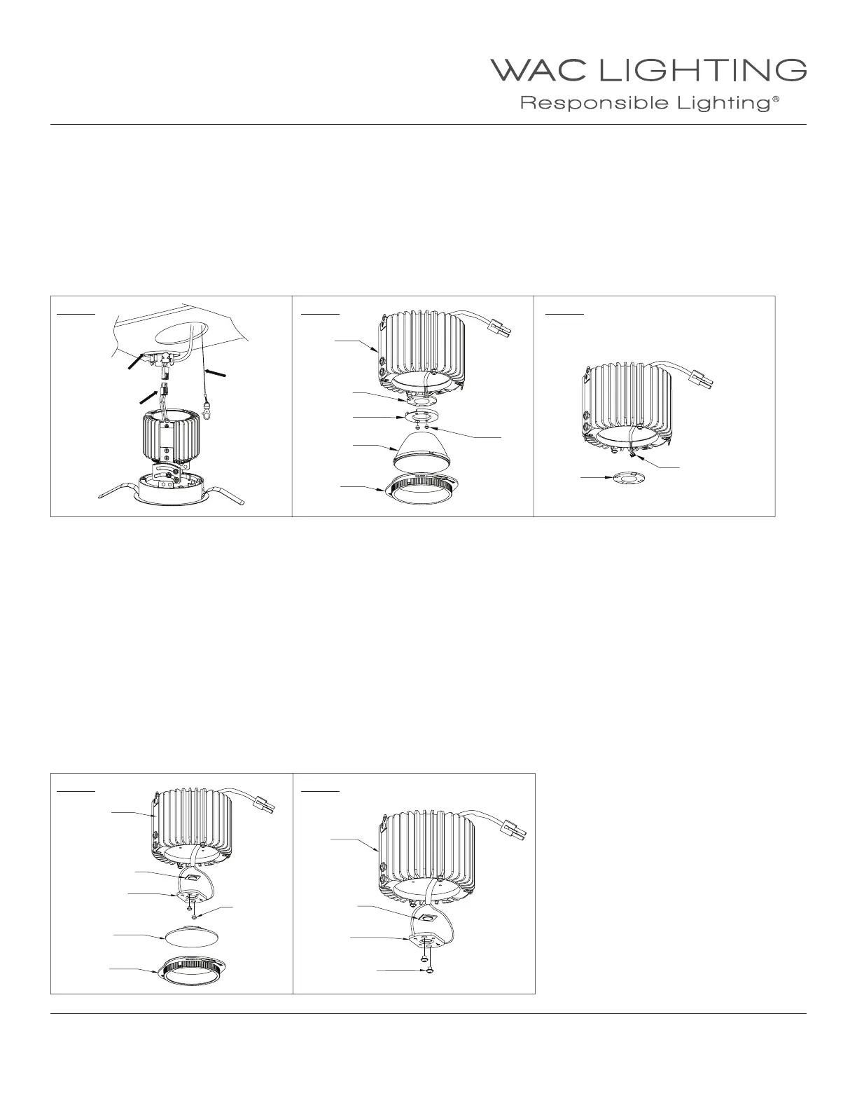
c. Remove cap and disconnect power connector and safety cable (See FIG.21).
d. Unlock and remove the optical cartridge and reector (See FIG.18).
e. Unscrew the LED holder and remove the LED connector from the LED module (See FIG.22, 23).
f. Remove and discard the LED module from the heat sink.
g. Coat the heat paste (by others or call the factory) on the back of the new LED module and place it on the heat sink by aligning two holes
on LED with two screw holes on the heat sink.
h. Connect the LED module with connector and fasten the LED holder on top of the LED model by tightening two screws.
i. Reinstall the reector and optical cartridge (See FIG.18)
j. Connect power connector and safety cable, then reinstall the trim assembly and trim inside xture to complete.
4. Replace the LED module (For Spot Beam)
a. Remove trim from the trim assembly rst, then the trim assembly from the ceiling or xture aperture (See FIG.19).
b. To remove the Trimless assembly, use the Philips-Head screw driver to unlock the locking screw, then use the at head screw
driver to release the spring tab on aperture ring (See FIG.20).
c. Remove cap and disconnect power connector and safety cable (See FIG.21).
d. Unlock and remove the optical cartridge and lens (See FIG.18).
e. Unscrew and remove the LED holder (See FIG.24).
f. Remove and discard the LED module from the heat sink.
g. Coat the heat paste (by others or call the factory) on the back of the new LED module, then mount the LED onto the LED holder.
Make sure the LED positive matching the holder positive (See FIG.25).
h. Place back the LED holder on the heat sink by tightening two screws.
i. Lock the optical cartridge on the heat sink.
j. Connect power connector and safety cable, then reinstall the trim assembly and trim inside xture to complete.
FIG. 21
FIG. 24
FIG. 22
FIG. 25
FIG. 23
Cap
Power
Connector
Heatsink
Heatsink
Safety Cable
Heatsink
LED
LED
LED
LED
LED Holder
LED Holder
LED Holder
LED Connector
Reector
Optical Lens
Screws
Screws
Screws
Optical
Cartridge
Optical
Cartridge
 Loading...