This document is an Operation & Maintenance Manual for a Wacker Neuson ST11 Compact Track Loader.
Function Description
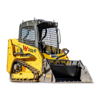
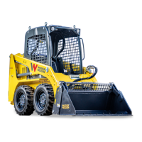
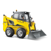
The Wacker Neuson ST11 is a compact track loader designed for various operations including loading, unloading, digging, and filling. It is equipped with a shovel for material handling and can be fitted with other authorized accessories for diverse tasks. The machine features hydrostatic drive with double axial piston pumps and variable cylinders connected to two-speed geared motors for each track roller, ensuring precise movement and maneuverability. Hydraulic servo-controls with joysticks facilitate the traversing and operation of the arms and bucket. A floating electrovalve adjusts the bucket to the ground, and a safety electrovalve blocks arm descent for enhanced safety.
Important Technical Specifications
Engine:
- Brand and Model: Kubota V1505T
- Calibration Power: 41 HP / 30 kW at 2800 rpm
- Cylinders: 4
- Displacement: 1498 cm³
- Cooling: Water
Hydraulic System:
- Main Variable-Cylinder Axial Piston Pump: 57.4 x 2 Lt/min
- Auxiliary Gear Pump: 39 x 1 Lt/min
- Total Capacity: 153.8 Lt/min
- Useful Capacity for Power Take Off (PTO): 39 a 180 bar Lt/min
- Max. Operating Pressure: 180 bar
- Hydrostatic Steering: Yes
Frame:
- Chassis in box-type sheet steel and shaped
Rubber Tracks:
Performance:
- Weight (fully equipped, including operator): 2220 Kg
- Bucket Capacity (SAE capacity): 0.245 m³
- 35% T.L. (*) ISO 14397/1-2: 400 Kg
- 50% T.L. (*) ISO 14397/1-2: 520 Kg
- (*)T.L.= Tipping Load = Max load permitted by the machine with maximum working radius at tipping limit.
- Tear Strength at Tooth: 930 daN
- Lifting Force at Floor Level: 1030 daN
- Transfer Speed I/II: 4.5 ÷ 10 Km/h
- Possible Gradient: > 100%
- Specific Ground Pressure (empty): 0.33 Kg/cm²
- Specific Ground Pressure (loaded): 0.40 Kg/cm²
- Autonomy: Approximately 8 hours
Hydraulic Power Takeoff (PTO):
- Plane Face Quick Couplings: 3/8"
- Work Pressure: 180 bar
- Pump Capacity: 39 l/min
Electrical System:
- Voltage: 12 V
- Absorption: 80 Ah
Overall Dimensions:
- Length: 2905 mm
- Width: 1218 mm
- Height: 2720 mm
Usage Features
The ST11 is designed for operator safety and ease of use. It features a ROPS and FOPS 1st level open cabin, with options for a cabin door, lateral window, and heating plant. The machine must only be driven by qualified staff aged 18 or older, with the safety bar lowered and safety belts fastened.
Starting and Stopping:
- To start, insert the key, turn clockwise to position "1", wait for the spark-plug pre-heating warning light to switch off, then turn to position "3". The key automatically returns to "1" after starting.
- To stop, turn the key anticlockwise to "0". It is advisable to idle the engine for a few minutes before stopping.
- The machine can only be started with the safety bar raised (Position "A"), which deactivates servo-controls and blocks lifting arms. Lowering the safety bar (Position "B") activates servo-controls and allows arm control (after pressing the activation button).
Movement and Maneuvering:
- Traversing is controlled by the left joystick.
- Straight Line Movement: Position A (Forward), Position B (Reverse - acoustic safety device activated).
- Change of Direction: Position F (90° Right Turn), Position E (90° Left Turn).
- Progressive Turns: Position H (Progressive Right Turn in Forward Movement), Position G (Progressive Left Turn in Reverse Movement - acoustic safety device activated).
- Lifting Arm Control: Position I (Arms Descent), Position L (Arms Ascent).
- Shovel Control: Position M (Shovel Closure), Position N (Shovel Opening).
- Speed Control: Buttons S (fast speed) and T (slow speed) on the joystick grip.
- Power Take Off (PTO) Control: Buttons P, Q on the joystick grip.
Safety Features:
- ROPS and FOPS 1st level cabin: Protection against tipping and falling objects. 2nd level FOPS is optional.
- Safety Bar: Deactivates hydraulic servo-controls and blocks lifting arms when raised.
- Emergency Exit: Front opening and rear window of the cabin.
- Lifting Arm Safety Activation/Deactivation Switch: For safe operation of lifting arms.
- Lifting Arm Fluctuation Function: Activated with a button, but must only be used with arms and bucket on the ground to prevent immediate fall.
- Road Circulation Prescriptions: Includes flashing lights, shovel blocking pin, shovel edge protections, plate positioning, and frame number punching area. Working system commands must be blocked, and working lights switched off.
Special Conditions of Use:
- Muddy, Humid, Snowy Terrain: Check hermetic seals, clean machine, check nuts/screws, and for cracks.
- Marine Terrain: Check hermetic seals, wash with sweet water to prevent corrosion, inspect electrical system.
- Dusty Terrain: Periodically check/clean air filter, alternator terminal board, starter, and water/oil radiator.
- Rocky Terrain: Use with caution, gentle maneuvers, use reinforced buckets, check articulations/joints/pins/fastenings.
- Icy Terrain: Use suitable fuel/lubricants for low temperatures, antifreeze, periodically check battery, protect tires.
Maintenance Features
The manual emphasizes that maintenance operations must be carried out exclusively by qualified personnel. An hour counter on the dashboard registers working time to facilitate maintenance scheduling.
General Maintenance Principles:
- Always ensure all safety precautions are taken before working on the machine.
- Clean the machine with the engine cold, using pressurized water. Avoid solvents.
- Dispose of oil and other liquids through authorized waste disposal.
- Hydraulic system inspections should be done with oil at operating temperature (around 60°C).
Specific Maintenance Operations:
- Cabin Raising: For maintenance, the cabin must always be blocked using a special supplied base level (Position 1 to Position 2).
- Shovel Lifting Arms Safety: An analogue safety system (ref. 3) inside the engine hood must be installed when shovel lifting arms are raised to prevent uncontrolled descent.
- Engine Hood: Features a lever "A" for shutdown and blocking in a completely open position.
- Engine Maintenance: Refer to the Manufacturer's Use and Maintenance booklet for the diesel engine.
- Refueling: Fuel tank capacity is 42 liters. Use a fine metallic mesh filter when filling. Avoid completely emptying the tank.
- Cooling System: Radiator at the rear, above the diesel engine. Check cooling liquid level when the engine is cold. Expansion tank cap "A" and radiator filling cap "C". Pressure detected for fan connection "1" must be 100 bar.
- Diesel Engine Lubrication System: Use supplied funnel "2" for oil introduction, discharge pipe "3" for draining. Never dispose of used oil in the environment.
- Engine Air Suction Plant: Air filter "A" at the rear. Luminous warning light (Fig. 1 - ref. 7.7) signals inefficiency. Cartridge "D" replacement involves releasing handles "C", removing cover "B", turning cartridge to release, cleaning with dry air (max 3 bar), and cleaning body "E" and cover "B". Replace cartridge every 6/8 months or according to work environment.
- Drive Transmission: Hydrostatic motor-reducer activates each track. Oil checks, filling, and replacement for wheel reducers are specified. First oil change after 100 hours, then every 1000 hours or annually.
- Hydraulic System: Oil tank in the rear central part, filling cap "D", visual level indicator "A". Tank capacity is 30 liters. Oil level checked with machine level and cylinder rods at maximum extension.
- Exhaust Filter: Replace filter cartridge "FS" after 100 hours for the first time, then refer to the maintenance table.
- Hydraulic System Pressure Calibration: M16 x 2 quick-coupling fittings for checking pressures. Points 1, 2, 3, 4 for traversing (300 bar), point 5 for services (180 bar), point 6 for servo-controls (24 bar). Calibration must be done by specialized personnel.
- Electrical System: Battery under the seat (12V, 80Ah). Use distilled water for top-ups. Disconnect earth wire (-) first, then positive wire (+).
- Grease Points: Principal greasing points indicated in the scheme, to be supplied every 8 hours, except for those with different indications. Track supporting rollers are permanently lubricated and do not require periodic greasing.
- Tightness of Nuts and Bolts: Periodically check tightness of main parts. Resistance class 8.8 for nuts and bolts. Driving torques provided for M6 (1÷1.2 daNm), M8 (2.3÷3.0 daNm), M10 (4.5÷5.3 daNm), M12 (7.8÷9.0 daNm), M14 (13÷14 daNm), M16 (20÷21 daNm).
Maintenance Table Summary:
- Cleaning: Air filter cartridge, radiator finning, silencer and shovel, gas oil filter cup, diesel fuel tank, hydraulic oil tank (frequencies vary).
- Checking: Motor cup oil level, coolant level, battery level, hydraulic oil level, air filter (stoppage spy), wheel reduction gear oil level, track roller tension (daily for new tracks, then as needed), alternator belt, fifth wheel, pins and articulated joints, electrical and hydraulic circuit (frequencies vary).
- Replacement: Engine oil, engine oil filter cartridge, diesel fuel filter cartridge, diesel fuel pre-filter, hydraulic oil and in-tank filter, coolant, hydraulic oil filter (cartridge), alternator belt, wheel reduction gear oil and air filter cartridge (frequencies vary).
- Greasing: Grease points (every 8 hours).
- Overhaul: Partial overhaul every 2000 hours (4 years), total overhaul every 5000 hours (10 years).