Do you have a question about the WACO DCM-30 and is the answer not in the manual?
Specifies ranges, resolution, accuracy, input impedance, and overload protection for DC voltage measurements.
Details ranges, resolution, accuracy, input impedance, and overload protection for AC voltage measurements.
Outlines ranges, resolution, accuracy, open circuit voltage, and overload protection for resistance measurements.
Describes audible indication, overload protection for continuity testing.
Covers ranges, accuracy, sensitivity, and overload protection for frequency measurements.
Explains test current, accuracy, open circuit volts, and overload protection for diode testing.
Details ranges, accuracy, and overload protection for AC current measurements.
Explains how to use the MAX DATA HOLD button to toggle the mode and display the MAX annunciator.
Guides on connecting leads, setting range, and interpreting readings for voltage measurements.
Instructions for using transformer jaws to measure current and selecting appropriate ranges.
Steps for performing resistance and continuity tests, including power removal and probe placement.
Procedures for setting the range, connecting leads, and reading frequency measurements.
Describes how to test diodes using the meter, including polarity and expected results.
Instructions for replacing the 9-volt battery, including warnings and screw removal.
The Waco DCM-30 Digital Clamp Meter is a versatile instrument designed for various electrical measurements, offering a range of functions for both professional and DIY use. Its primary function is to measure AC current without breaking the circuit, thanks to its clamp design. Beyond current, it also measures DC and AC voltage, resistance, and frequency, and includes features for diode testing and continuity checks.
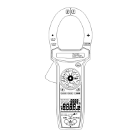
The DCM-30 operates as a digital clamp meter, allowing non-contact measurement of AC current by clamping its jaws around a single conductor. This eliminates the need to disconnect the circuit, enhancing safety and convenience. The meter features a clear 3½ digit liquid crystal display (LCD) that shows readings up to 1999, with automatic polarity indication for DC measurements. An "OL" or "-OL" display indicates overrange conditions, while a " " symbol signals a low battery, prompting replacement.
For voltage measurements, the meter can handle both AC and DC voltages. Users connect test leads to the designated "VΩ" and "COM" jacks, then select the appropriate voltage type (AC or DC) and range using the function/range switch. If the voltage magnitude is unknown, it's recommended to start with the highest range and gradually reduce it until a stable reading is obtained. For DC voltage, a negative sign indicates negative polarity, while positive polarity is implied.
Resistance and continuity measurements are performed by setting the function/range switch to the desired resistance range or continuity position. Before testing, power to the circuit under test must be removed. Test leads are connected to the "VΩ" and "COM" jacks and then touched to the test points. In resistance mode, the display shows the measured value. For continuity tests, a continuous beeper sounds if the resistance is less than 30Ω, indicating a closed circuit.
The diode test function allows users to check the integrity of diodes. With the function/range switch set to the diode position, test leads are connected to the "VΩ" and "COM" jacks. Probes are touched to the diode, and a forward-voltage drop (typically around 0.6V for a silicon diode) is displayed. Reversing the probes should display "OL" if the diode is good. A shorted diode will show ".000" or another low number, while an open diode will display "OL" in both directions. If the diode is measured in a circuit and a low reading is obtained with both lead connections, it suggests the junction might be shunted by a resistance of less than 1kΩ, in which case the diode should be disconnected for accurate testing.
Frequency measurements are performed by setting the function/range switch to the "Hz" position. Test leads are connected to the "VΩ" and "COM" jacks and then to the point of measurement to read the frequency from the display.
The DCM-30 is designed for user-friendliness and safety. It includes a MAX DATA HOLD button, which, when pressed, toggles the meter into MAX DATA Hold mode, displaying "MAX" on the LCD. This feature is useful for capturing and retaining the maximum reading, though it is disabled in frequency count mode, even if "MAX" is still displayed.
The meter emphasizes safety, advising users to always inspect the meter and test leads for damage or defects before use. It is intended for low-energy circuits up to 600VDC or 600VAC, or high-energy circuits up to 250V AC or DC, and is not recommended for high-voltage industrial use beyond these limits. Users are cautioned to turn off power to the circuit before making any connections that could be hazardous. When working with voltages above 60V DC or 30V AC rms, users should exercise caution due to shock hazards. When using probes, fingers should be kept behind the finger guards. The meter also warns against measuring voltages that exceed its limits, as this can damage the device and pose a shock hazard to the operator.
For current measurements, the function/range switch should be set to the highest 600A AC range initially. The trigger is pressed to open the transformer jaws, which are then clamped around a single conductor. For maximum accuracy, the conductor should be placed at the center of the closed jaws. If the reading is below 200 counts, the range switch should be moved to the next lower range position to ensure optimal accuracy without over-ranging the meter.
Maintenance of the DCM-30 is straightforward, primarily involving battery replacement. The meter is powered by a standard 9-volt "transistor" battery (NEDA 1604, IEC 6F22). The low battery indicator " " appears on the LCD when the battery needs replacement. To replace the battery, users must first remove the test leads for safety. One screw on the back of the meter is removed to lift off the battery case, allowing access to the battery contacts for replacement. The manual explicitly warns to remove test leads before changing the battery or performing any servicing to prevent electrical hazards. The meter is designed for operation in environments from 0°C to 40°C with less than 70% relative humidity, and for storage from -20°C to 60°C with 0 to 80% relative humidity, provided the battery is removed.
| Continuity Check | Yes |
|---|---|
| Jaw Opening Size | 30mm |
| Power Supply | 9V battery |
| Type | Clamp Meter |
| Display | LCD |
| Power Source | Battery |
| Operating Temperature | 0°C to 40°C |
| Storage Temperature | -10°C to 50°C |