carga debe incluir también la fusión requerida para
cumplir con los requerimiento de protección del
circuito bifurcado del Código Eléctrico Nacional o
el equivalente local. Si se ha instalado, la opción de
falla del contactor debe estar en “ON”.
NC, NO y COM
Estas terminales se conectan a la salida del relé. El
relé se cierra cuando la línea de voltaje está en la
tolerancia seleccionada, cuando el control de
voltaje está en funcionamiento y cuando el
cronómetro de demora ha expirado. Típicamente
Ud. conectaría las terminales COM y NO en series
con el control de circuito, con el arranque del motor
o con la bobina del contactor.
C1, C2 y C3
los pares de voltaje normales AB BC CA.
Conecte un control del voltaje a C1 y C2. El DTP-3
responde al voltaje entre 18 y 250 Voltios y provoca
Presionando una vez el botón SELECT se
sólo una fracción de un Amper. Una carga de
muestra el voltaje del lado de la carga del
anticipación interna es provista conectando C2 a
contactor (si la opción del lado de carga está
C3 para permitir el uso de un termostato de 24
conectada). La pantalla regresa
Voltios. Asegúrese de conectar C3 sólo para 24
automáticamente a la pantalla del voltaje de lado
Voltios o menos.
de la línea después de pocos segundos.
CONFIGURACION
Presione el botón SELECT para pasar por los
El DTP-3 debe ser previamente configurado en un
parámetros. A medida que pasa por los
negocio u otro lugar simplemente aplicando
parámetros, el parámetro seleccionado
energía a cualquiera de los tres pares de fases del
destellará. Use las flechas ascendentes y
lado de la línea. El DTP-3 se activará con energía
descendentes para ajustar el valor de
de fase individual y permitirá la configuración de
funcionamiento deseado.
los parámetros del usuario en un sistema trifásico
antes de la instalación.
Voltaje del lado de la línea
Después de completar la instalación (o para una
Voltaje del lado de la carga
configuración única) aplicar energía al DTP-3. La
Nivel de voltaje
pantalla del DTP-3 mostrará una prueba breve
Tolerancia de voltaje superior/inferior en %
de la pantalla seguida del número de revisión del
Tolerancia de Desequilibrio de Voltaje en %
firmware (programa impreso en los circuitos
Tiempo de bloqueo en segundos
electronicos, realizado por la empresa y que no
Tiempo de demora en segundos
puede ser modificado por el usuario). El DTP-3
Tiempo de respuesta en segundos
indicará entonces el tiempo restante o cualquier
Modo de control
cronómetro activo. Si los cronómetros han
Monitor de fallas del contactor
expirado el voltaje de línea será puesta en
Pantalla de memoria de fallas
pantalla. Los indicadores de SOBRE VOLTAJE,
BAJO VOLTAJE, PERDIDA DE FASE y/o de la
Adecuación de Parámetros (para exhibir en la
INVERSION DE FASE pueden ser visibles
pantalla) Pantalla activa de Voltaje de Línea (este
también dependiendo de las configuraciones de
es la pantalla normal de fallas)
fábrica en relación a su línea de voltaje entrante.
Nivel de Voltaje
En cualquier momento durante el funcionamiento
(VAC Flashes) El valor puede ser ajustado
del DTP-3 Ud. puede leer el voltaje entrante
presionando las flechas ascendentes y
presionando el botón SELECT para regresar al
descendentes. Esto puede ser configurado para
voltímetro AB BC CA (Presentación Normal)
el voltaje de funcionamiento normal del
dispositivo, siendo protegido en los incrementos
de un Voltio.
LA PANTALLA
Normalmente la pantalla muestra los voltajes de
Tolerancia de Mayor /Menor Voltaje en %
línea AB BC Y CA
(Flashes de BAJO VOLTAJE/SOBRE VOLTAJE)
El valor puede ser ajustado presionando las
Si la unidad está esperando a un cronómetro, el
flechas ascendentes y descendentes
cronómetro será mostrado en la pantalla. La
pantalla del cronómetro puede apagarse
Tolerancia de Desequilibrio de Voltaje en %
presionando SELECT. La LCD mostrará entonces
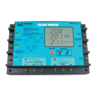
The DTP3’s
LCD DISPLAY
RESP.
LOCK OUT TIME
% IMBALANCE
DELAY
SECONDS
MINUTES
CONTACTOR FAULT
UNDERVOLTAGE
OVERVOLTAGE
PHASE IMBALANCE
OFF
ON
AUTO
PHASE LOSS
PHASE REVERSAL
VAC
FAULT
C-A
B-C
A-B
MEM
LINE SIDE
LOAD SIDE
que el tiempo de respuesta ha expirado, el DTP-3 metálica con cuatro tornillos de metal laminado
apagará su relé de salida y protegerá su Nº 8. El montaje sobre una superficie metálica
dispositivo. ayuda a disipar el calor y a proteger al DTP-3
de la radiación de equipos cercanos.
Cuando el relé del DTP-3 se abre, el cronómetro
de demora se activa. Este cronómetro mide el CABLEADO
tiempo pasado desde que la salida fue apagada y Si el voltaje que está siendo monitoreado está
previene al equipo protegido del riesgo de conectado a una fuente de alta corriente, la
reiniciarse demasiado rápido. La demora también protección del circuito de ramificaciones (
pue de ser regulada por el usu ari o. Es fusible o interruptor del disyuntor tal como es
particularmente útil para la protección de descrito en el Código Eléctrico Nacional)
compresores, en donde un intento de reinicio debería ser provista. Como la corriente dibujada
rápido puede causar un atascamiento y desgaste por el DTP-3 es una fracción de un Amper, la
del motor protección bifurcada puede ser seleccionada
para el tipo de cable utilizado. Típicamente los
DESCONECTE TODA ENERGÍA ANTES DE fusiles de 1 Amper proveerá la protección
COMENZAR LA INSTALACIÓN DEL DTP-3 requerida. Si el monitor del lado de la carga es
utilizado, su cableado debe ser también de
corriente limitada.
INSTALACIÓN
La instalación del DTP-3 es simple y directa DESCRIPCION DEL DIAGRAMA
L1, L2 y L3
MONTAJE Conecte el voltaje que está siendo monitoreado a
Escoja un lugar fresco y seco para el montaje las terminales L1, L2 y L3 del DTP-3. Este voltaje
del DTP-3. Recuerde que el frente de la unidad también suministrará energía al DTP-3 y deberá
posee los controles del operador y la pantalla venir desde una fuente como la del lado de la
digital. El frente del DTP-3 no debería quedar línea del contactor que está siendo controlado.
obstruido y debe permitir un fácil acceso a los
botones de control. Un lugar apropiado podría T1, T2 y T3
ser la cubierta del control, cerca del iniciador del Si su aplicación requiere monitoreo del lado de la
motor y el contactor del compresor carga del contactor, Ud. debe conectar el lado de
la carga del contactor a las terminales T1, T2 y T3
El DTP-3 debería montarse sobre una superficie del DTP-3. Fíjese que el monitoreo del lado de la
I
Linea de voltaje
a ser monitoreada
Connect C2 to C3
if control voltage is 24 Volts or less
Existing Controls
or Thermostat
Diagrama Tipico de Cableado
CARGA
CONTACTOR
MODEL DTP-3
VOLTAGE MONITOR
DELUXE THREE PHASE
A Division of DiversiTech
MANUFACTURING
L1
Phase A
L2
Phase B
L3
Phase C
90-600 VAC
PHASE TO PHASE
50/60 Hz
CONTACTOR
LINE SIDE
T1
T2
T3
CONTACTOR
LOAD SIDE
ADJUST
SELECT
Fault Memory:
READ: Select MEM (Blinks)
press up or down arrows to
select fault #
CLEAR: Select MEM (Blinks)
press and hold both up and down
for two seconds
OFF
ON
AUTO
Hold SEL Press DOWN
Hold SEL Press UP
Hold SEL Press UP & DOWN
DTP-3
L1
CONTACTOR
LOAD
T1
T2
T3
L2
L3
RELAY
CONTACTS
NO
COM
NC
10A 220V RES.
CONTROL
C1
C2
C3
18-277 VAC
Connect C2-C3
for 24 V T’Stat
Control Voltage
(From Transformer)
Fuses
Fuses
as required
see text
optional wiring
for load side monitoring
A
B
C
SIEMPRE PRESTAR EXTREMO CUIDADO CUANDO SE INSTALE O
AJUSTE EL EQUIPAMIENTO UTILIZANDO VOLTAJES PELIGROSOS !
forward.
MOUNTING
Select a cool, dry location for the mounting of
the DTP-3. Keep in mind that the front of the
unit has the operator controls and the digital
display. The front of the DTP-3 should be clear
of obstructions and allow easy access to the
control buttons. A suitable location may be in
the control enclosure, near the motor starter or
compressor contactor.
The DTP-3 should be mounted on a metal
surface with four #8 sheet metal screws.
Mounting on a metal surface helps dissipate
heat and shield the DTP-3 from nearby
C1, C2 and C3
equipment radiation.
Connect a control voltage to C1 and C2. The
DTP-3 responds to voltage between 18 and
WIRING
250 Volts and draws only a fraction of an Amp.
If the voltage being monitored is tapped from a
An internal anticipator load is provided by
high current source, branch circuit protection
connecting C2 to C3 to allow the use of a 24
(fuse or circuit breaker as described in the
Volt thermostat. Be sure to only connect C3
National Electric Code) should be provided.
for 24 Volt or lower operation.
Since the current drawn by the DTP-3 is a
fraction of an Amp, the branch protection can
SETUP
be selected for the wire type used. Typically,
The DTP-3 may be setup at a shop or other
fuses rated at 1 Amp will provide the required
location prior to installation by simply applying
protection. If the load side monitor option is
power to any of the three line-side phase
utilized, it’s wiring must also be current limited.
pairs. The DTP-3 will power up on single
phase power and allow the setting of user
PINOUT DESCRIPTION
parameters prior to installation in a three
L1, L2 and L3
phase system.
Connect the voltage being monitored to the
After completing the installation (or for stand-
DTP-3’s L1, L2, and L3 terminals. This voltage
alone setup), apply power to the DTP-3. The
will also power the DTP-3 and should come
DTP-3 display will show a brief display test
from a source such as the line side of the
followed by the firmware revision number.
contactor being controlled.
The DTP-3 will then indicate the remaining
time on any active timers. If the timers are
T1, T2 and T3
expired the incoming line voltage will be
If your application requires contactor load side
displayed. The OVERVOLTAGE,
monitoring, you should connect the contactor
UNDERVOLTAGE, PHASE LOSS and/or the
load side to the DTP-3’s T1, T2 and T3
PHASE REVERSAL indicators may also be
terminals. Note that the load side monitoring
visible depending on the factory settings
should also include the required fusing to meet
versus your incoming line voltage.
the branch circuit protection requirements of
the National Electric Code or locale equivalent.
During any point in the DTP-3’s operation,
If installed, the contactor fault option should be
you may read the incoming voltage by
set to “ON”.
pressing the SELECT button to return to the
AB BC CA voltmeter. (Normal Display)
NC, NO and COM
These terminals connect to the relay output.
The relay closes when the line voltage is within
the selected tolerance, the control voltage is on
and the delay timer has expired. Typically you
would connect the COM and NO terminals in
series with the control circuit, motor starter or
contactor coil.
THE DISPLAY
The display normally shows the AB BC and
CA line voltages.
If the unit is waiting on a timer, that timer will
be displayed. The timer display may be
switched off by pressing SELECT. The LCD
will then display the normal AB BC CA voltage
The DTP3’s
LCD DISPLAY
RESP.
LOCK OUT TIME
% IMBALANCE
DELAY
SECONDS
MINUTES
CONTACTOR FAULT
UNDERVOLTAGE
OVERVOLTAGE
PHASE IMBALANCE
OFF
ON
AUTO
PHASE LOSS
PHASE REVERSAL
VAC
FAULT
C-A
B-C
A-B
MEM
LINE SIDE
LOAD SIDE
OVERVIEW
The DTP-3 Line Voltage Monitor provides Additionally, phase rotation is tested. If the
continuous monitoring of the power and rotation is reversed, operation of the output
control signals used to operate any three relay is inhibited.
phase load. Protected devices can include
motors, pumps, fans, compressors and other If any of the limits that you set are exceeded,
devices. the response timer will begin counting. You
also have the flexibility to set the response
The DTP-3 protects these devices by keeping timer -- a short time may be desired for a quick
a constant watch over the supplied voltage, response or a long time may be desired to
and when the voltage goes outside of a avoid nuisance tripping. If the voltage remains
voltage and tolerance that you select, the outside the tolerance after the response time
DTP-3 opens its control relay. has elapsed, the DTP-3 will turn off its output
relay and protect your device.
The time required to respond to the out-of-
tolerance conditions is user adjustable and When the DTP-3’s relay opens, the delay
may be set for shorter times for sensitive timer starts. This timer keeps track of the time
devices or longer times to help eliminate since the output was turned off and prevents
nuisance tripping. the protected equipment from restarting too
soon. The delay is also user adjustable. It is
Each of the three line voltage pairs are particularly useful for the protection of
checked for voltage level and phase to phase compressors, where an attempted rapid
balance. Further testing of the system restart can cause a stalled condition and
includes contactor-load-side monitoring. motor burnout.
When enabled, the load side monitor checks
the contactor for closure. If the contactor load DISCONNECT ALL POWER BEFORE
side voltage does not match the line side STARTING THE INSTALLATION OF THE
voltage to 5 volts within 0.5 seconds after the DTP-3
control relay closes, the control relay is
opened and remains locked out until power to INSTALLATION
the DTP-3 is cycled off and on. Installation of the DTP-3 is simple and straight
Line Voltage
to be monitored
Connect C2 to C3
if control voltage is 24 Volts or less
Existing Controls
or Thermostat
Typical Wiring Diagram
LOAD
CONTACTOR
MODEL DTP-3
VOLTAGE MONITOR
DELUXE THREE PHASE
A Division of DiversiTech
MANUFACTURING
L1
Phase A
L2
Phase B
L3
Phase C
90-600 VAC
PHASE TO PHASE
50/60 Hz
CONTACTOR
LINE SIDE
T1
T2
T3
CONTACTOR
LOAD SIDE
ADJUST
SELECT
Fault Memory:
READ: Select MEM (Blinks)
press up or down arrows to
select fault #
CLEAR: Select MEM (Blinks)
press and hold both up and down
for two seconds
OFF
ON
AUTO
Hold SEL Press DOWN
Hold SEL Press UP
Hold SEL Press UP & DOWN
DTP-3
L1
CONTACTOR
LOAD
T1
T2
T3
L2
L3
RELAY
CONTACTS
NO
COM
NC
10A 220V RES.
CONTROL
C1
C2
C3
18-277 VAC
Connect C2-C3
for 24 V T’Stat
Control Voltage
(From Transformer)
Fuses
Fuses
as required
see text
optional wiring
for load side monitoring
A
B
C
ALWAYS USE EXTREME CAUTION WHEN INSTALLING OR
ADJUSTING EQUIPMENT UTILIZING HAZARDOUS VOLTAGES !
Control de Voltaje
Controles existentes
o Termostato
Conectar C2 a C3, si el control de
voltaje es 24 Voltios o inferior.
Como se
sugiere en
el texto
La PANTALLA
del DTP 3 LSD
 Loading...