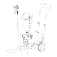
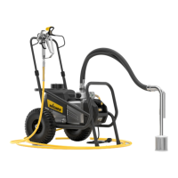
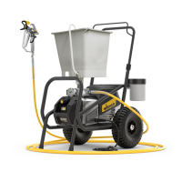
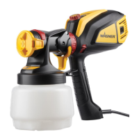
DESCRIPTION OF UNIT
3.2 EXPLANATORY DIAGRAM
1 Whip hose for injection work (a)*
Tip guard with airless tip for spray work (b)*
2 Gun*
3 High-pressure hose
4 Connection for high-pressure hose
5 Material ball cock:*
Open:
The material can be fed
Closed: The material
cannot be fed
6 Pressure control valve
7 ON/OFF switch
8 Indicating lamp (green indicates presence of line voltage)
9 Discharge tap to regulate the ow of the material:
Open (discharge tap points down):
The material is fed into the hopper
Closed (discharge tap at 90°):
The material is fed to the gun or to the
material ball cock.
10 Return tube
11 Hopper
12 Inlet valve button
13 Outlet valve
14 Oil measuring stick
15 Pressure gauge
* Accessories
5
8
1b
1a
2
3
7
12
4
6
10
11
13
9
14
15
 Loading...