43
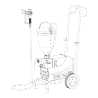
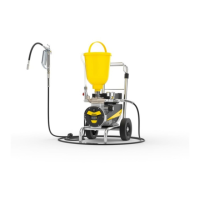
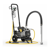
Super Finish 33 PLUS/PRO • Nespray Pro
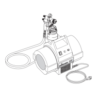
REPLACING A 400 V CORD SET
1. Ensure safe isolation from the supply before commencing work.
2. First of all loosen the strain relief until the cable can be freely moved.
3. Disconnect the defective cable, noting the exact pin assignment.
4. Strip the new cable to the desired length, taking care not to damage the insulation of the individual wires.
5. First shorten wires L1, L2, L3 and N by 1.5 cm. This ensures that when there is a tensile load on the cable, the protective con-
ductor (PE) is disconnected last.
6. Now strip the individual wires to the desired length.
7. Now press the wire end ferrules on, making sure that the wires terminate ush with the sleeve and that no individual wires
protrude.
8. Now connect the cable in accordance with the pin assignment noted in point 3. Make sure that secure contact is achieved.
9. Now tighten the strain relief - but not too much, as this could cause the cable or an individual wire to shear o .
10. After completing the repair a measurement in accordance with BGV A3 must be carried out, in order to ensure electrical
safety and functionality. See chapter 1.4
3.3 REPLACING THE CAPACITOR
1. Ensure safe isolation from the supply before commencing work.
2. Remove the wires (plug connector on capacitor).
3. Loosen the xing nut on the front of the capacitor.
4. Remove the capacitor.
5. Now install and connect the new capacitor in the reverse order.
6. After completing the repair a measurement in accordance with BGV A3 must be carried out, in order to ensure electrical
safety and functionality. See chapter 1.4.
7. The defective component must be made inoperative in order to prevent further use.
3.4 REPLACING SWITCHES / BUTTONS
1. Ensure safe isolation from the supply before commencing work.
2. Remove the individual wires at the switch, noting the contact con guration.
3. Remove the switch, noting its installation position.
4. Install the new switch.
5. Establish the electrical connection, observing the contact con guration of point 2.
6. After completing the repair a measurement in accordance with BGV A3 must be carried out, in order to ensure electrical
safety and functionality. See chapter 1.4
7. The defective component must be made inoperative in order to prevent further use.
GB
 Loading...