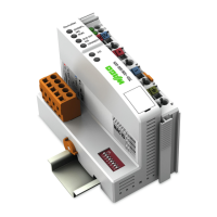
Do you have a question about the WAGO 750-375 and is the answer not in the manual?
Provides essential safety precautions for installing and operating the device.
Details the power supply requirements, including isolation and system supply.
Details the general specifications and PROFINET IO properties of the fieldbus coupler.
Provides instructions for safely inserting and removing devices, emphasizing de-energization.
Describes the process of device start-up, hardware tests, and initialization phases.
Explains the basic structure of process data exchange and submodule types.
Describes the operation of PROFIsafe V2 I/O modules and their diagnostics capabilities.
Explains the use of the iPar server for saving and restoring parameters for quick device replacement.
Details the PROFIenergy profile for energy management and controlling output modules.
Provides instructions for updating the device firmware using the WAGO Ethernet Update tool.
Provides an overview of the process and steps required for commissioning the IO device.
Details the steps for hardware configuration and parameterization of the IO device.
Explains how the IO controller establishes the PROFINET connection and initiates cyclic data exchange.
Lists the specific steps for configuration after complete installation of the IO device.
Covers parameterization requirements for hardware configuration and setting parameters for the fieldbus coupler and I/O modules.
Details the structure of application and communication relationships (AR and CR) for PROFINET connection.
Explains the exchange of cyclic process data, alarms, and acyclic demand data after system start-up.
Explains the function of the LEDs on the fieldbus coupler for indicating operational status.
Describes how the system responds to fieldbus failures and internal data bus failures.
Lists various types of digital input, output, input/output, analog, specialty, and system modules.
Details individual attribute values and descriptions for parameterizing various I/O modules.
| Manufacturer | WAGO |
|---|---|
| Model Number | 750-375 |
| Bus System | PROFIBUS DP |
| Isolation | 500 V |
| Color | Gray |
| Transmission Rate | 9.6 kBd ... 12 MBd |
| Storage Temperature | -25 … +85 °C |


