Do you have a question about the WAGO 750-652 and is the answer not in the manual?
Details the applicability of the documentation to specific I/O modules and variants.
States copyright protection and usage restrictions for the manual.
Explains the meaning of various symbols used in the documentation for warnings and notes.
Defines how numbers are represented (decimal, hex, binary) in the document.
Explains the meaning of different font styles used in the manual.
Covers legal aspects such as subject to changes, personnel qualifications, and compliance.
Explains that devices are supplied with pre-configured hardware/software.
Lists essential safety precautions for installing and operating the device.
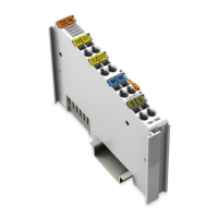
Provides a visual overview and identification of the module's components.
Details the various connectors on the module, including data and power jumper contacts.
Explains the meaning of the LEDs indicating operating status and communication.
States that the module has no operating elements.
Presents the electrical schematic diagram of the module.
Details technical specifications for device data, supply, communication, interface, and environment.
Lists all granted certifications and markings for the module.
Details compliance with EMC and marine application standards.
Explains how data is stored and controlled in serial transmission modes.
Explains how data is stored and controlled in data exchange mode.
Details how the I/O module functions as a link for serial communication.
Explains the process of transmitting data via the I/O module.
Explains how data is received by the I/O module and transferred to the application.
Details the RS-232 operating mode, including flow control options.
Details the RS-485 operating mode, including switching time.
Details the RS-422 operating mode and flow control.
Details the DMX operating mode, its capabilities, and specifications.
Explains the cyclic data exchange between modules.
Describes the procedure for mounting modules on a carrier rail.
Provides instructions for inserting and removing I/O modules from the carrier rail.
Details how to connect conductors using the CAGE CLAMP® system.
Illustrates connection examples for various operating modes like RS-232, RS-485, and RS-422.
Explains how to configure the module using the WAGO-I/O-CHECK software.
Mentions alternative configuration methods via GSD files for specific fieldbus systems.
Introduces chapters describing data transfer in serial and data exchange modes.
Lists common diagnostics and their solutions for serial operating modes.
Lists diagnostics and solutions for the data exchange operating mode.
Shows examples of module markings for ATEX, IEC-Ex, and NEC compliance.
States the need to follow valid installation rules for hazardous areas.
Details specific safe use conditions for ATEX, IEC-Ex, and ANSI/ISA certifications.
Explains GSD file configuration and PI module type selection for PROFIBUS/PROFINET.
Shows examples of configuration dialogs for PROFIBUS/PROFINET couplers.
Details parameter assignments and diagnosis behavior for PROFIBUS/PROFINET couplers.
| Product type | Fieldbus Coupler |
|---|---|
| Category | Recording Equipment |
| Bus System | PROFIBUS DP |
| PROFIBUS DP | Yes |
| Input current (5 V system supply) | 100 mA |
| Number of modules per node | 64 |
| Input Voltage | 24 V DC |
| Protection Class | IP20 |
| Product Name | 750-652 |
| Data transfer rate | 9.6 kbit/s to 12 Mbit/s |
| Number of slaves | Up to 125 |
| Operating Temperature | -25 °C to +60 °C |