12 Quickstart Description WAGO-I/O-SYSTEM 750
750-880 ETHERNET Programmable Fieldbus
Quickstart Reference
Version 1.0.0
Pos: 14 /A ll e Ser ien ( Al lg emei ne M od ule)/ Über s chrif te n für al le S eri en/Sc hnel ls tart besc hrei bung - Üb erschr ift 1 @ 9\mod_1287492268613_21.doc @ 65713 @ 1 @ 1
3 Quickstart Description
Pos: 15 /S eri e 7 50 ( WA GO-I/ O-SYST EM) /Ger ät ebesc hrei bu ng/Ei nlei tu ng/Fel d busko ppl er/-c ont roll er/ Einl eit end er Te xt/ Quic ks tar t/St arter Ki t 75 0-0880: Auf bau der Har dw are Ü 2 u nd Ei nl eit ung @ 1 3\mod_1348142899039_21.doc @ 103066 @ 2 @ 1
3.1 Hardware Design
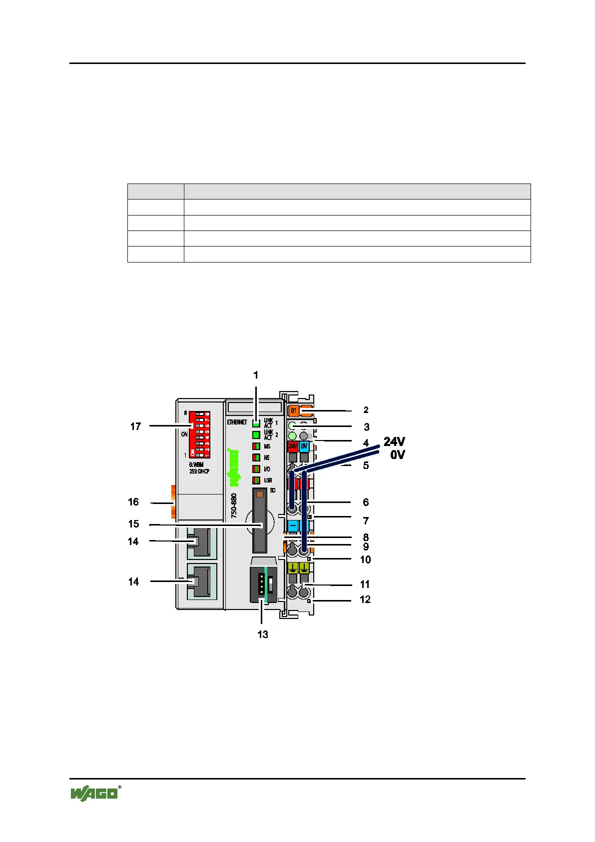
The fieldbus node is to be structured as follows (viewed from left to right):
Table 3: Fieldbus Node Structure
The 24VDC power supply unit is linked to the power (24V and 0V) for the
fieldbus controller and for the power jumper contacts (see No. 5 in the figures of
the PLC views and connections below).
For the application used in the example, it is sufficient to connect a jumper
between "24V" and "+" (see No. 6) or between "0V" and "-" (see No. 9).
Figure 1: View and 24V/0V connection of the ETHERNET-TCP/IP fieldbus controller
Pos: 16 /Doku menta tion all gemei n/Gli eder ungsel emen te/---Seit en wechs el--- @ 3\mod_1221108045078_0.doc @ 21810 @ @ 1

 Loading...