Do you have a question about the WAGO WAGO-I/O-SYSTEM 750 750-362 and is the answer not in the manual?
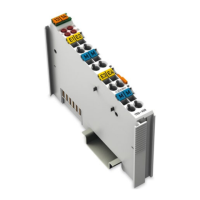
| Protection Class | IP20 |
|---|---|
| Power Supply | 24 V DC |
| Number of Channels | Not applicable |
| Input Voltage | Not applicable |
| Input Current | Not applicable |
Specifies that installation and operation must be done by qualified electrical specialists.
Outlines essential safety precautions for installation and operation, including working de-energized.
Provides guidelines for using ETHERNET devices, emphasizing local network use and security measures.
Details power supply requirements, including overcurrent protection for system and field supply.
Explains the need for external fuse protection to prevent damage and fire hazards.
Covers the requirement for a 24 VDC system supply and its protection.
Recommends regulated power supplies for stable voltage quality and how to determine supply capacity.
Explains how sensors and actuators connect to I/O modules and the role of power supply modules.
Describes connecting sensors and actuators and powering them via I/O modules.
Details internal fusing options for various field voltages using appropriate power supply modules.
Covers external fusing for 24V field supply using automotive fuse modules.
Explains the 24 VDC system supply requirement and recommends regulated power supplies.
Covers grounding procedures for the DIN rail, including framework and insulated assembly.
Details grounding the DIN rail via framework assembly or insulated assembly.
Explains grounding the carrier rail by screwing it to a conducting cabinet or frame.
Explains how grounding contacts increase resistance to EMI and dissipate it to the carrier rail.
Discusses using shielded cables to reduce electromagnetic interference and improve signal quality.
Recommends using shielded signal lines for analog and I/O modules to ensure accuracy.
Describes how the device is powered via terminal blocks and the galvanic separation of the fieldbus interface.
Explains the device is powered via terminal blocks with CAGE CLAMP® connections.
Details the fieldbus connection via two RJ-45 ports, supporting 10/100 Mbit.
Explains how the address selection switch assigns a fixed IP address by setting the host ID.
Lists technical specifications for the device, system, supply, fieldbus, accessories, and connection types.
Details supply-related technical data such as voltage, input current, efficiency, and isolation.
Specifies technical data for the Fieldbus Modbus TCP, including process image sizes.
Lists granted approvals for the device, including conformity marking and Ex approvals.
Lists EMC requirements and standards for emission and immunity to interference.
Discusses mounting components onto carrier rails following EN 60175 (DIN 35) standard.
Outlines guidelines for carrier rails, including material, electrical properties, and stability.
Describes the sequence for mounting fieldbus couplers and I/O modules, including safety precautions.
Provides safety instructions for insertion and removal, emphasizing de-energizing the device.
Details the procedure for inserting the fieldbus coupler/controller onto the carrier rail.
Explains the process for removing the fieldbus coupler/controller using the release tab.
Describes how to insert I/O modules into the assembly until they snap into place.
Step-by-step guide for connecting a PC to fieldbus nodes, including mounting and power supply.
Explains methods for assigning IP addresses: Switch, DHCP, WAGO Settings, BootP.
Explains enabling DHCP via switch or software and network requirements for DHCP servers.
Step-by-step guide to enable DHCP using WAGO Ethernet Settings when no IP address is known.
Instructions to enable DHCP via WBM "TCP/IP" page when an IP address is known.
Describes using WAGO Ethernet Settings for IP configuration via serial or ETHERNET interface.
Explains using a BootP server for IP assignment, its protocol, and system requirements.
Details permanently assigning an IP address using the static configuration option in WBM.
Explains how to update the device firmware using the "Update" WBM page.
Covers configuring network addressing and identification on the "TCP/IP" WBM page.
Details specifying settings for the Modbus protocol on the "MODBUS" WBM page.
Describes fault behavior for fieldbus and local bus failures, including LED indications.
Explains fieldbus connection failure due to watchdog timeouts, master issues, or cable interruptions.
Details local bus failure indications via I/O LED blink codes and output module behavior.
Details BootP for assigning IP addresses and parameters to head stations via TCP/IP networks.
Explains DHCP for assigning IP addresses and parameters, its advancement over BootP, and operating modes.
Introduces Modbus as an open fieldbus standard and its functions.
Provides a general overview of Modbus protocol implementation and its functions.
Details FC1 for reading input/output bits (coils) and their request/response structure.
Explains FC2 for reading input bits from slave devices, including request/response.
Describes FC3 for reading holding registers in word format, including request, response, and exception.
Details FC4 for reading input registers in word format, covering request, response, and exception.
Explains FC5 for writing a single output bit to a slave device, including request, response, and exception.
Describes FC6 for writing a single output register value in word format.
Explains FC15 for setting a sequence of output bits to 1 or 0 in a slave device.
Describes FC16 for writing a sequence of registers in word format to a slave device.
Displays Modbus addressing and internal variables for register access reading and writing.
Lists various Modbus registers with their addresses, access types, lengths, and descriptions.
Details the Modbus watchdog for monitoring communication regularity and preventing lapses.
Describes Modbus watchdog registers for setting timeout values and triggers.
Illustrates marking examples for ATEX, IECEx, NEC, and CEC according to hazardous area classifications.
Shows marking examples for Europe compliant with ATEX and IECEx standards for hazardous areas.
Provides marking examples for NEC and CEC compliance in hazardous areas in North America.
Details installation and operation regulations for electrical equipment in hazardous areas.
Highlights warnings and requirements for installing products in hazardous areas, including enclosure limits.
Lists additional requirements for ANSI/ISA Ex compliance, including use in Class I, Division 2.