©2011 Warn Industries, Inc.WARN® and the WARN logo are trademarks of Warn Industries Inc. 4 76454 A1
INSTALLATION INSTRUCTIONS
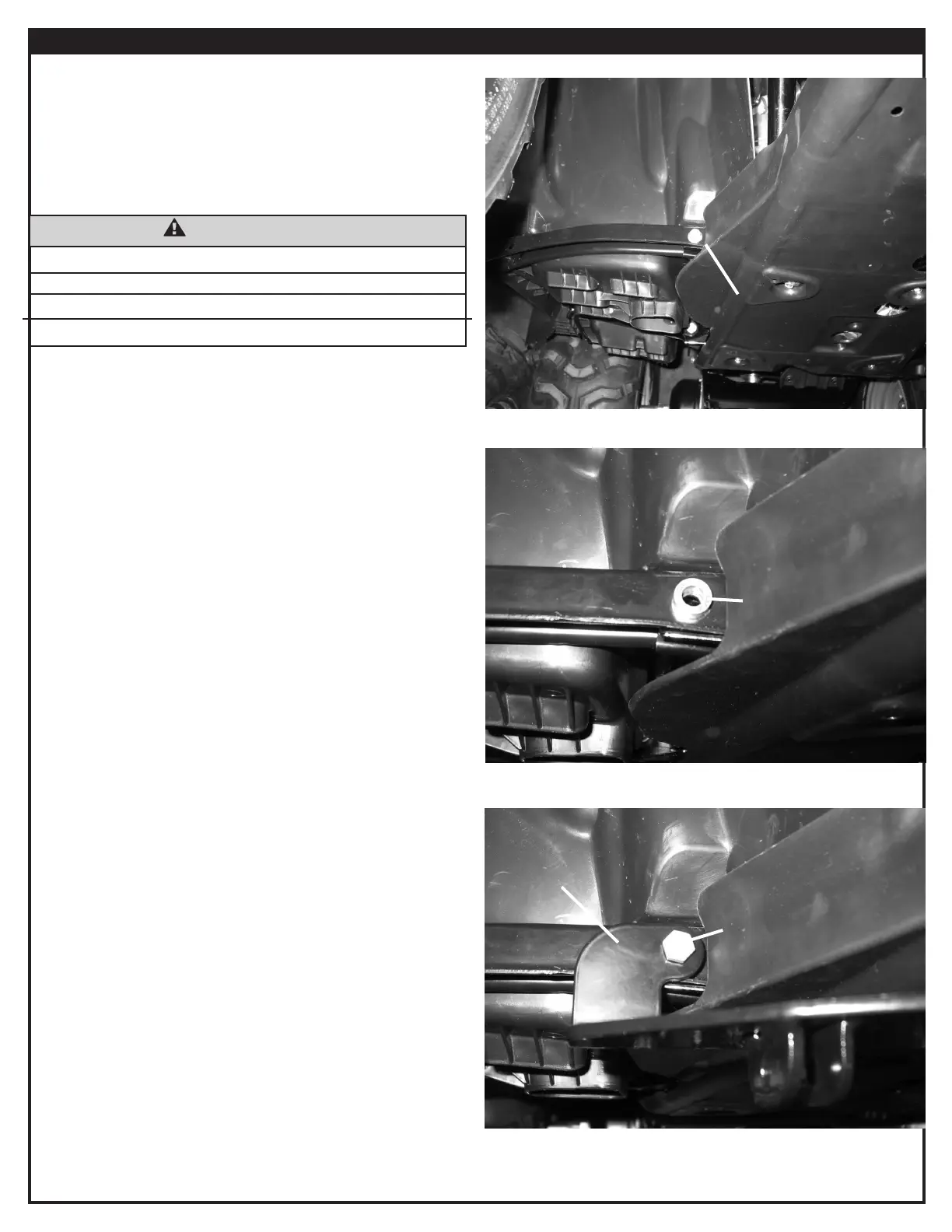
1. Remove the two outer M8 oorboard bolts, gure 1. Keep
the M8 nuts for reassembly.
2. Place the 1/4” spacers (B5) into position over the
oorboard bolt holes, gure 2.
3. Place the plow mount (A1) into position over the spacers
(B5), gure 3. Loosely secure the plow mount with two M8
X 45mm bolts (B4), 5/16” washers (B2), and the M8 nuts
removed in step 1.
Note: Do not tighten at this time.
Note: On the 475cc (500) models, trimming of the plastic
may be required to get placement of the mount positioned
correctly to mark location of the u-bolts.
Figure 1 - Remove Bolts
Figure 2 - Position Spacers
Figure 3 - Plow Mount Location
Remove
B5
A1
B4 & B2
WARNING
IMPACT AND MOVING PARTS ENTANGLEMENT HAZARD
Failure to observe these instructions could lead to severe injury or death
• Always remove jewelry and wear eye protection.
Read installation and operating instructions thoroughly.