©2011 Warn Industries, Inc.WARN® and the WARN logo are trademarks of Warn Industries Inc. 6 76454 A1
INSTALLATION INSTRUCTIONS
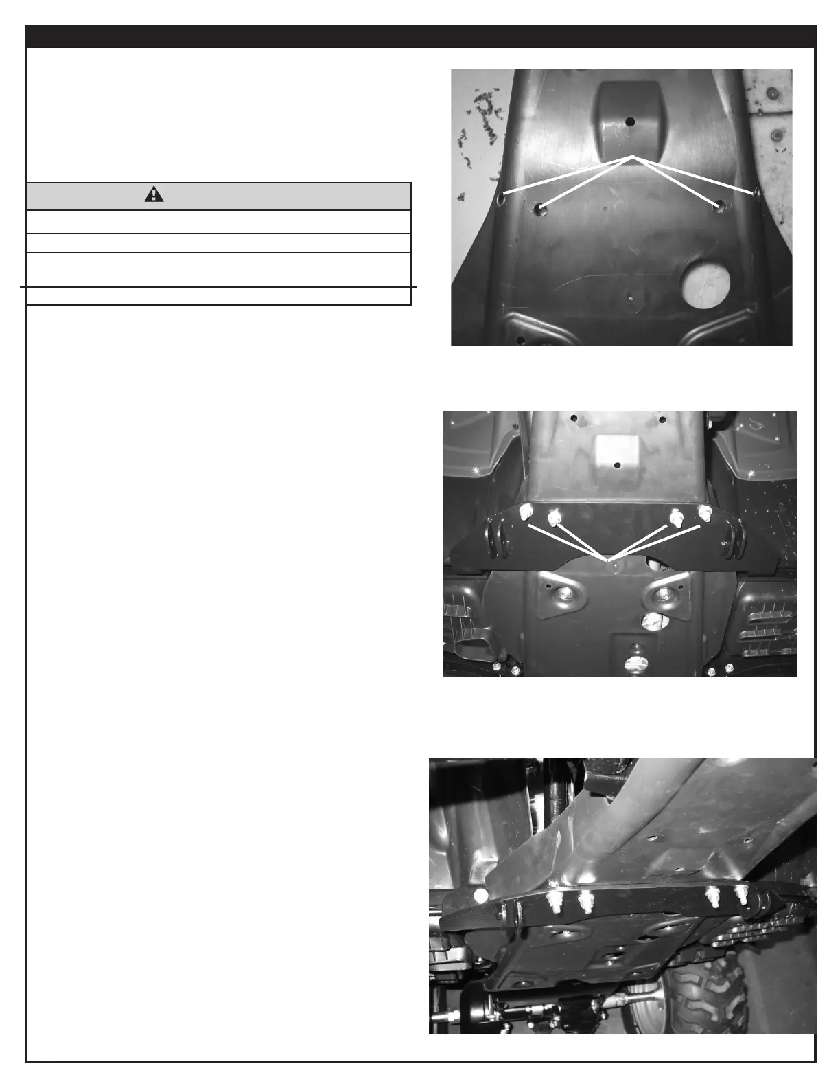
Figure 8 - U-Bolt Check
Holes
B1, B2, & B3
7. Mark the location of the u-bolts, as noted in step 6, on
the slots scribed onto the skid plate. Use the marks as
reference to drill four clearance holes for the u-bolts in the
plastic skid plate, gure 7.
8. Loosely fasten the skid plate onto the vehicle. Repeat steps
2 and 3 to loosely fasten the plow mount. Slide the two
u-bolts (B1) around the frame tubes and through the skid
plate and plow mount, gure 8. Loosely fasten the u-bolts
with the four 5/16” at washers (B2) and four 5/16-18 lock
nuts (B3).
Note: If the u-bolts do not pass freely through the plastic skid
plate, then remove the plow mount and skid plate. Use a
round le to enlarge the holes for the u-bolts as necessary.
Repeat step 8 once the holes have been adequately
modied.
9. Tighten all hardware (M6 skid plate bolts, 5/16-18 lock
nuts, M8 bolts, and M8 nuts) to the recommended torque
values found on page 2.
Figure 7 - Skid Plate Holes
Figure 9 - Plow Mount Installed
WARNING
IMPACT AND MOVING PARTS ENTANGLEMENT HAZARD
Failure to observe these instructions could lead to severe injury or death
• Always wear safety glasses when installing this kit. A drilling operation will cause
yingmetalchips.Flyingchipscancauseeyeinjury.
Read installation and operating instructions thoroughly.
 Loading...